
Base
| Full Name | Ranjeet Kumar |
| Organization | |
| Job Title | student |
| Country |
Forum Replies Created
Hi Dhiman,
I think we doesn’t need to change different parameters while shifting from NRZ to RZ or vice-versa.
There is some difference between them.
You should use same parameters for both coding techniques.
thanks,
Hi,
I would suggest you to
apply dense wavelength division multiplexing
(DWDM) to the system will be a strong candidate
in order to support all of BS’s for fiiture fiber-optic
access network infrastructure. There have been
several reports on such DWDM radio-on-fiber
systems [I]-[3]. To increase the spectral efficiency
of the system, the concept of optical frequency
interleaving was first proposed by Schaffer et al.
by simultaneous upconversion scheme with an
electro-optic modulator [4]. Recently, a simple
method to increase the spectral efficiency by
optical frequency interleaving was proposed in
which the modulation format could be either
optical double side band (DSB) or optical single
side band (SSB).The transmitted signal (A) is fed to a
high-Finesse Fabry-Perot etalon (FP) through an
optical circulator (OC). Thc free spcctral range of
the FP is adjusted to cqual to the channel spacing.
Thanks,
Hi Remo De Suza,
I will suggest you to use advanced modulation formats like: CSRZ, DRZ and MDRZ at transmitter end.
Because CS-RZ format has high tolerance to the mixed effect of self phase modulation(SPM)and group velocity dispersion(GVD)andhasnarrowerpedestalshapeof the opticalspectrumthantheconventionalRZformat.
IncaseofCSRZ transmitter,the NRZ optical signal after MZ modulator goes through phase modulator, The
duobinary precoder used here is composed of an
exclusive-orgatewithadelayed feedback path.DRZ
formats are very attractive,because their optical
modulation bandwidth can be compressed to the data
bit rateB,thatis,thehalf-bandwidthoftheNRZ
format2B. The generation of MDRZ signal is almost identical to the
DRZ signal,exceptthedelay-and-addcircuitisreplaced
by adelay-and-subtract circuit. In the duobinary signal
used earlier where thephase of bits‘1’s are modified
only after a bit‘0’appear where as in the modified
duobinary signal the phase is a lternated between 0 and p
for the bits‘1’.The phase of all the‘‘zero’’bits are kept
constant and a 180 degree 1 phase variation between all the
consecutive‘‘ones’’is introduced [5]. A l so optical signal
spectrum Fig.1(3b) shows that th ecarrier of the
duobinary signal has been suppressed.
Hi Sahil singh,
Yeah, I agree with thepoints that BER results will chane with changing types of signal.
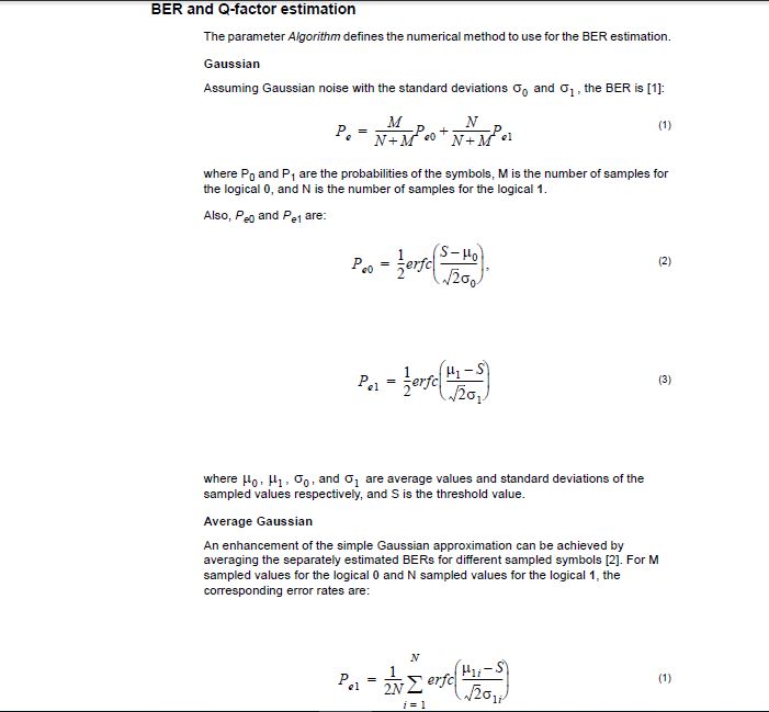
Here i am uploading the image which contains the formula of calculations of BER and Q-factor.
The two parameter Algorithm defines the numerical method to use for the BER estimation namely Gaussian and average gaussian.
In this we could see the factor on which BER depends are where P0 and P1 are the probabilities of the symbols, M is the number of samples for the logical 0, and N is the number of samples for the logical 1, average values and standard deviations of the sampled values respectively, and S is the threshold value.If the signal is mixed with the noise, the Average Gaussian method is modified to calculate the average error patterns. The the Average Gaussian method can estimate the BER per bit or per pattern, the Worst-case Gaussian searches for the min BER for each bit or pattern instead of calculating the average values
So, BER depends upon types of signals.
Hope i could explain it correctly.
Seeking your response.
Attachments:
H Remo De Suza,
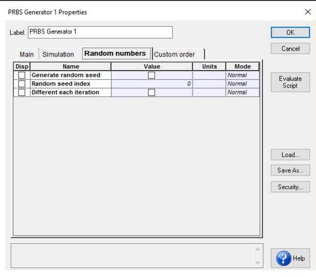
In optisystem we have Generate random seed which Determines if the seed is automatically defined and unique and also Random seed index
User-defined seed index for noise generation.
As in the BER test set we have multiple binary sequence generation options namely a PRBS generator, User Defined sequence generation, or external Sequence. The PRBS and User Defined sequence generators are exact copies of the PRBS and User Defined sequence components respectively whose default values for the number leading and trailing zeros is not the same. The PRBS generator inside the BER test set takes its number of leading and trailing zeros from the layout parameters and has default values of 0. The PRBS component defines the leading and trailing zeros within its own component and has default values of “(Time window * 3 / 100 ) * Bit rate”. This can make a big difference. Try setting them the same for a better comparison. For now, if you need to generate a random seed each calculation, you can set the BER Test Set, to choose “external component” and connect a PRBS component to it.
Seeking your response.
Attachments:
Hellow Dhiman Kakati,
I think that in latest version of optisystem i.e. 14th , we could not design Space division Multiplexing as it is a channel access method based on creating parallel spatial pipes. It is mostly used for MIMO Systems, Smart antenna and 5G.
I don’t think it has any application in optical fiber communication.
It is used in combination with TDM, FDM and CDM.
Hi Khadija Omran,
As you have also pointed that “And Why when use it must the SMF length is 5 times the length of DCF “.
I think from above explanations you should understand that condition of SMF length is 5 times than that of DCF is not necessary.
It will vary according to dispersion parameters and length of fiber both.
Hope this will help you.
seeking your quick response.
Hi Khadija Omran,
As we know that during the propagation of a pulse through the fiber, the group velocity dispersion (GVD) changes the frequency across the pulse referred to as frequency chirp. The chirp depends on the sign of the dispersion parameter. And the frequency chirp is negative, the frequency decreases across the pulse from the leading to the trailing edge if the dispersion coefficient parameter is positive.
The relation between dispersion parameter of SMF and DCF and their length is given by:
D1*L1 + D2*L2 = 0.
D1 and D2 are dispersion parameters of SMF and DCF respectively and L1 and L2 are their length.
From above equation D2 will be always negative as D1 is positive.
Yeah Ubaid, Share a very good.
LPF also removes noise and interference which gets mixed with signal during its transmission through medium needs to be removed.
Hence LPF is a very important components at receiver ends, Its type may vary according to its applications and type of receivers.
Hi ZULKARNAIN,
The eye diagram is not proper to analyze.
I think you should change the values of different global parameters.
You should check whether PBRS data rate is less than global data rate.
As many requested you to upload your osd file, so that we will help you.
Seeking your response.
Hi Rifat,
Damian Marek sir has explain the generation of optical-frequency-comb-optical-system.
Thanks to Damian sir such valuable sharing information.
Hi,
I also agree that the size of RAM doesn’t create problems in simulation in case of optisystem.
Optisystem software is not so bulky one.
I think you have some problem in your design.
Seeking your response.
You are most welcome Remo De Suza
As You have pointed out your problems of simulation results, although it was not so serious one.
I will try to help you as per my ability.
Hi,
I agree to the points of Dhiman sir which he try to explain about the differences between SMF and Bidirectional fiber.
In case of bidirectional fiber , signals are transmitted in both direction simultaneously but with both having different frequencies.
In this we have a provision of optical delay.
Hi SAHIL SINGH,
I think i am right because what i have learnt and read the optisystem software and its information datasheet. I didn’t find something relevant to the measurement of Refractive index of materials in optisystem.
Hope we will have an option to measure Refractive index of materials in near future.