
Base
| Full Name | Abhishek Shrama |
| Organization | NITTTR |
| Job Title | Asst proff. |
| Country |
Forum Replies Created
Welcome Mohammad Namera 🙂 Thanks for Big regards.
From now even in case you are in any doubt for any question than you easily get to know by visiting Help section.
For the visulizers you will not get this help tab,because in case you double click ,results will be displayed to you.Than you can just right click on component and go to the properties than help tab is there for visulizers
Regards
Hi SAM
In my reply for which you are asking is just a assumption that i made by searching the profile designer optiwave.I got the mannual of FDTD and there is description of same.Then only i posted the comment.But since author work on optiwave optiBPM, it is also possible in both the versions. By the way thanks for pointing me out 😉
Hi! Mahammad
Welcome
Kindly Click on SMF (Fiber) and there is help button on the extreme right downside.Just click on it and you will check the component detail.Help section is for every component ,you can check the basic information even equations from which these components realized.Also there are articles which considered as a base while designing the components.
Thank you
Hi! Dhiman Kakati
Suggestion made above is good as it solved your problem.But it is not quite obvious that works every time.However the increase in sequence length increase the accuracy of calculation and show less fluctuations as in the case of lower seq. length 128.So using longer sequence length for any system makes it more accurate but due to increase in total no of samples it take more time .
Thank you
Hello Mohammad Namera
Sometimes result change in same version too, Due to the random seed generation of some components.By just deselecting random seed results comes out to be every time.
Secondly ,i think if system has lower sequence length then results may fluctuate in other version with all same parameter and file.But these results should be vary little not too much.If your results change to great extent than you should ask Damian to check it.
Thank you
Hi! Mohammad namera,I think this would be the case that author didnt get desired power at output.Since it works fine for me without any issue.Thank you for your help
I just did basic calculation and got desired results
Kindly run the file by closing other application .Since the error which screenshot you have attached shows that file is used at multiple programs.In another case sometimes file not downloaded completely and we start running it ,this may be the case here.Rest let me know if it than also exits.Then optiwave or Damian will address you.
Hi Sasha
I want to know that ,while changing the input wavelength have you changed the reference frequency of fiber? Since you are getting output in 1200 t0 1550 nm then it also works for other wavelengths. Regardless performance of the system may degrades at wavelength which lies other than C band.I dont have latest version so could not open your file ,however i will try to attach the screen shot of file i will try to make for all the wavelengths you stated above in your question.
Regards
I have copied the information ,just look it and see if it helps
The optical fiber component simulates the propagation of an optical field in a single-mode fiber with the dispersive and nonlinear effects taken into account by a direct numerical integration of the modified nonlinear Schrödinger (NLS) equation (when the scalar case is considered) and a system of two, coupled NLS equations when the polarization state of the signal is arbitrary. The optical sampled signals reside in a single frequency band, hence the name total field. The parameterized signals and noise bins are only attenuated.
Dispersion file format
Determines contents of dispersion file: group delay or dispersion vs. wavelength. If “Dispersion vs. wavelength” and “Frequency domain parameters” are selected, it is assumed that file containsβ2 λ. If “Frequency domain parameters” is disabled, component assumes that file contains D λ. If “Group delay vs wavelength”, the file contains β1 λ.
Hi Sasha
Kindly look at the Help section ,there is detailed information on dispersion and all the effects in optical fiber along with equations.As far as i know if you look at the optical fiber dispersion tab by double clicking on smf,there is file which is fixed and used for dispersion vs frequency.Which changes foe the input wavelength
Since i am using a older version of optisystem so could not able to upload the system file.However as i stated above by taking value of attenuation 0.2dB/Km (default in optical fiber lib. component SMF) you can test it.
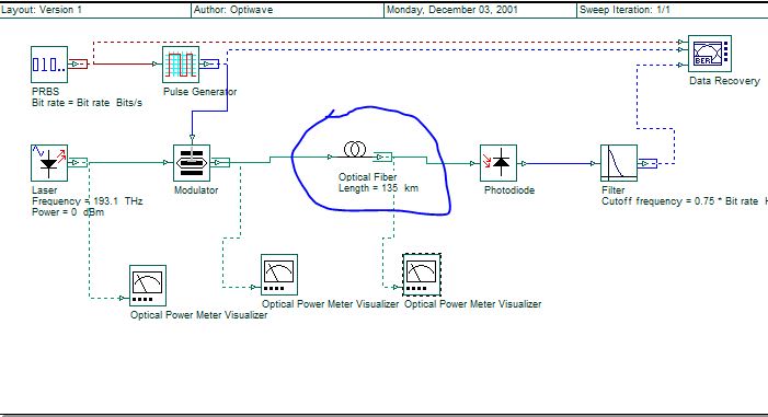
Kindly see the screen shot of the system ,i have calculated the value of fiber as
135Km x 0.2dB=27dB
Which corresponds to the attenuation value at attenuator
Attachments:
Hi Sasha
The optisystem sample file that you have attached is providing results to me in required manner.In file the attenuater is set to 27dB and overall power after attenuation is -30.010.Transmitter laser power is 0dB and after MZM comes out to be -3.010dB due to insertion losses and all.
I have tried by deleting attenuator and inserted a SMF of same attenuation i.e 27dB .I got the same results with fiber and attenuation.Value at BER is also same order of 10^-9
Try it as i said and if there is than any problem let me know
Thank you
Dear Subash Arya
If i am getting you right,then reducing the layout size can be done by just clicking on layout size on menu bar.You just click it and fill the dimensions in it, and get the desired layout window.
Secondly if you want to add your simulation system to any manuscript or paper and it is of long size then you can reduce it by clicking at View>zoom percentage and you can select the % which cover your whole system and then snip it.
Thirdly if you want to change size of the subsystem(box which include some component) the you just click it on and drag the either side of box and stretch to increase and decrease it.
Hope i have covered all the possibilities and it will help you
Regards
Thank you Gaganpreet,Could you please attach the .osd file if you made this? It it hard for me to set the values of MZM and since you are working on it ,so it would be better if you attach file.
Thank you
Thank you Damian for reply, link Damian has suggested is very good for the topic, give you information how encoder and decoder works.In below link one of the forum member also described the coding ,kindly check