
Base
| Full Name | Philip Weetman |
| Organization | Optiwave |
| Job Title | Research Scientist: OptiSystem |
| Country |
Forum Replies Created
Hi Adnan,
Yes, it probably isn’t available in the examples anymore because as of OptiSystem 13, new OFDM components have been created, which are much more realistic and flexible for different modulation and symbol formats. Take a look in “Documents\OptiSystem 14.1 Samples\Advanced modulation systems\OFDM systems” to see the new OFDM designs.
Hi Esakki,
Let me sketch out the way the power combiner works right now.
Assume we have a 2 port combiner with signals only at a single carrier frequency. Let E1(t) = A1(t)exp(jwt) and E2(t) = A2(t)exp(jwt). Where E1(t) is the input field in port 1, E2(t) is the input field in port 2. The carrier frequency is w. Thus the modulated amplitude is A1(t) for port 1 and A2(t) for port 2. The phase information is carried in A1(t) and A2(t) by allowing them to be complex numbers.
Now, if you require power to be conserved, the output port field cannot simply be Eout(t) = E1(t)+E2(t) = [A1(t)+A2(t)]exp(jwt) because (ignoring other factors) Pout = |A1(t)+A2(t)|^2 which will not equal Pin = |A1(t)|^2 + |A2(t)|^2. Therefore, for power conservation, the output field will have to be renormalized so that the output field is instead Eout(t) = N(t)[A1(t)+A2(t)]exp(jwt).
It turns out that there are actually physical reasons why the normalization factor N(t) exists and you can show (for example) for a symmetric waveguide Y-junction, N(t) = 1/sqrt(2). The problem here is that the power combiner is not a specific physical device, but an idealized model. In fact, one of our BPM and FDTD experts is at the moment looking at designing a physical-based power combiner device.
So the question then becomes, what are you going to use for the normalization factor? The way it works right now is we define
N(t) = sqrt(|A1(t)|^2 + |A2(t)|^2)/|A1(t)+A2(t)| (***of course with checks to make sure we are not dividing by zero***). From the argument above, you see that indeed power will be conserved when you use this as this is simply the factor by which the power is off by. However, as you quite rightly point out, the phase information is lost. Dividing by |A1(t)+A2(t)| essentially “normalizes out” any phase difference.
If you divided by ||A1(t)|+|A2(t)|| instead, you will retain phase information. That is, if both signals are in phase, Pout = Pin as above, but if the signals are 180 degrees out of phase, Pout = 0. I have tested this and it works. If you have some phase in between 0 and 180, you will have 0<Pout<Pin as you would expect. Now, is this a reasonable normalization? It works as you would expect for phase differences of 0 and 180 deg and gives you qualitatively what you’d expect for phases in between. It is also becomes the correct factor of 1/sqrt(2) in the perfectly symmetric case. Maybe its the best we can do?
I have tentatively modified the power combiner to have 3 options:
1. The old method: N(t) = sqrt(|A1(t)|^2 + |A2(t)|^2)/|A1(t)+A2(t)|. For users who want to enforce power conservation in all cases.
2. The phase-dependent method N(t) = sqrt(|A1(t)|^2 + |A2(t)|^2)/||A1(t)|+|A2(t)||. As discussed above, doesn’t always conserve power.
3. The symmetric device N(t) = 1/sqrt(2). Only conserves power when both input signals have identical amplitudes and phases. This is analogous to Wilkinson power divider/combiner.
I have also made similar modifications to the other combiners with more ports with the appropriate sums of amplitudes and powers over all ports. The symmetric device is now N(t) = 1/sqrt(n).
Sorry about writing all the equations inline, I didn’t want to attach a multitude of image files!
Thoughts?
Hi Esakki,
Thanks for the input about the phases. I will take a look at it. Feel free to email me at Philip.Weetman@optiwave.com and we can discuss it further.
We have tried to make it straightforward to use even if one is not too familiar with C++. We encourage users to experiment with translating their MatLAB components to C++ if they are interested in the performance boost.
One of the main challenges of translating scientific code from MatLAB to C++ is finding equivalent numerical procedures to those supplied by MatLAB. We have supplied some functions in the project and we are very open to adding any mathematical functionality desired by the user. We may even have those desired procedures already embedded in OptiSystem itself, which we could extract.
Hi Prakash,
The distortion is a major issue with this research. It will depend on many factors: refractive index and doping profiles, signal modes used, pumping modes used, etc … We have provided a tool for the calculation and we are interested in seeing the designs the research community can create. I’d recommend you search through the literature and see which configurations have been studied.
These components can be used in FSO with appropriate designs.
Hi Alitsu,
As of OptiSystem 14.0, the power combiner and the ideal MUX will now both simply add the powers. In fact at multiple wavelength input, the power combiner will act exactly like an ideal MUX. Of course, the power combiner can also add signals of the same wavelengths.
The previous method for the power combiner was based on a Wilkinson power divider/combiner model which we decided wasn’t appropriate.
Really? Could you show us a snip of what you are doing? Here is what I got for the optical power combiner. 4 inputs at 10W gave 40W output.
Attachments:

Hi Guys,
We have now implemented some SDM capabilities in OptiSystem 14.0.
– We have rewritten our multimode Er and Yb doped amplifiers to calculate mode-dependent gain correctly. You will notice that it runs longer than our old component, this is because there are many spatial overlap integrals that must be performed to get an accurate calculation.
– We have created a new “Spatial Demultiplexer” component, which demultiplexes both wavelengths and spatial modes. Right now the spatial mode separation is just “ideal”, no coupling between the different spatial modes. In the future we would like to add some coupling or even try to simulate something like a photonic lantern.
– Damian has created an OptiSystem project for a two mode SDM example. It is in our samples folder.
We invite all of you to give it a try and let us know what you think!
If you don’t want to optimize the system as shown in Damian’s link, but would rather use a gain flattening filter, see:
Hi Roman,
In this case I had no leading or trailing zeros.
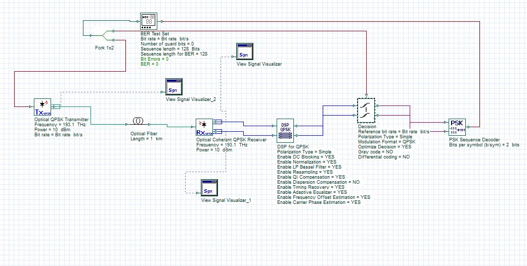
In addition to the threshold detection of the M-ary, the “Decision” component performs functions such as: Constellation rotation, Alignment and Polarization rotation … check out the help section for this component, it has lots of good information.
I didn’t bother with “Dispersion compensation” because your fiber was only 1km in length. You can add it if you wish.
It’s not surprising that BER = 0. If your system has low enough noise (and a good enough DSP) that you have a BER like 10^-10, that means for every 10^10 bits, you will encounter one error. In this system, there were only 128 bits sent, so it is highly unlikely that you would actually encounter the bit error.
To measure BER, the straight counting like the BER test set will be the most accurate method, but for very low BER systems, your sequence length will need to be impractically large. If you don’t want such a large sequence length, then you have to use estimation techniques based on statistics (like our BER analyzer).
Hi Roman,
I will have to think about it. For now, would you like to try your system using our DSP and Decision component? I attach a diagram showing this.
Attachments:
If you need one right now, I would suggest you use MatLab or SciLab to create one. The transfer functions for these filters are available online in many places. If you can wait a month or so, OptiSystem 13 will have a number of additional filters including ‘root-raised cosine’ and ‘inverse sinc’ for both electrical and optical domains.
Hi Roman,
The BER from the BER Analyzer is calculated in a statistical manner (which it has to be for such small sequence lengths) from the size of the eye opening and the standard deviation of the pulses from the ideal positions. In your case, you have M-ary threshold detectors and psk decoders before the BER analyzer and thus the pulses are now at their ideal positions so there are no standard deviations and therefore zero BER.
So you should either modify your system so that the signal is sent to the BER Analyzer before being pinned at the thresholds or look at our BER test set, this component doesn’t estimate the BER, but does a straight counting, comparing initial signal to final signal. The drawback of the counting method of course is that it may take a very long sequence to actually see a bit error.
Hi Fernando,
Our DSP Components are designed such that you can use our algorithms or insert any of your own at each stage of the process, the only restriction is that you should use our downsampling. See the section “Inserting your own MATLAB algorithm” in the help documentation of the “DSP for 16QAM” and the “DSP for QPSK” for further information.
In OptiSystem 13, which will be released in June or July, we expand the capability to include non-linear compensation as well as BPSK,8PSK,16PSK and 64QAM modulation formats.
Can you expand on your second question?
Hi Jaffar,
You should be able to use the NRZ generator instead, but your optical output won’t look as good! There was an issue with the rise and fall times of the NRZ pulse generator, which generally does not effect things but here is noticeable. It has been fixed, and will be in the soon to be released update. So at this point I’d recommend staying with the PSK generator. You could write a small MatLab or Scilab component that will convert the M-ary signal to electrical. Or maybe the easiest solution is to upgrade to the latest 12.2.1?