
Base
| Full Name | Ibn Aziz |
| Organization | NUST |
| Job Title | Student |
| Country |
Forum Replies Created
Dear ABdullah Baig ,
if u want to publish in reputable Journals then following are considered as best Journals in Optical and photonics domai;
JLT (Journal of light Tech)
PTL (Photonics Tech letter)
Springer
Elsevier
Confrences
OFC
ECOC
P.s Every reputable Journal never takes any sort of money from you.
Best of luck
Regards
Thanks alot Ravil,
From where i can get these specifications ? i have searched alot and got number of specifications but don’t know which one is authentic.
1. For Splitter if i use 0.2 dB loss is that accurate ??
If i use above formula to get value of Loss then it would be very high and results in degradation of signal. This so because, i am using almost 5-8 splitters in my setup with 5 splitters with 2 output ports and 2 with 5 output ports. In this way my BER wil raises to much.
Ravil if i keep loss range of splitter between 0.2-0.5 it that ok/ meaningful ??
2. For optical combiner i am also using loss range between 0.2-0.5 dB, is that correct ??
3. for Optical band pass filter (gaussian) and electrical band passs filter , i kept the same value range between 0.2-0.5 db, Is this possible or Should i increase more ??
Thanks for ur participation in the topic and if u know above values or have some knowledge about above issue plz share.
Best regards
Best Regards
Thanks Jaffer for ur participation !
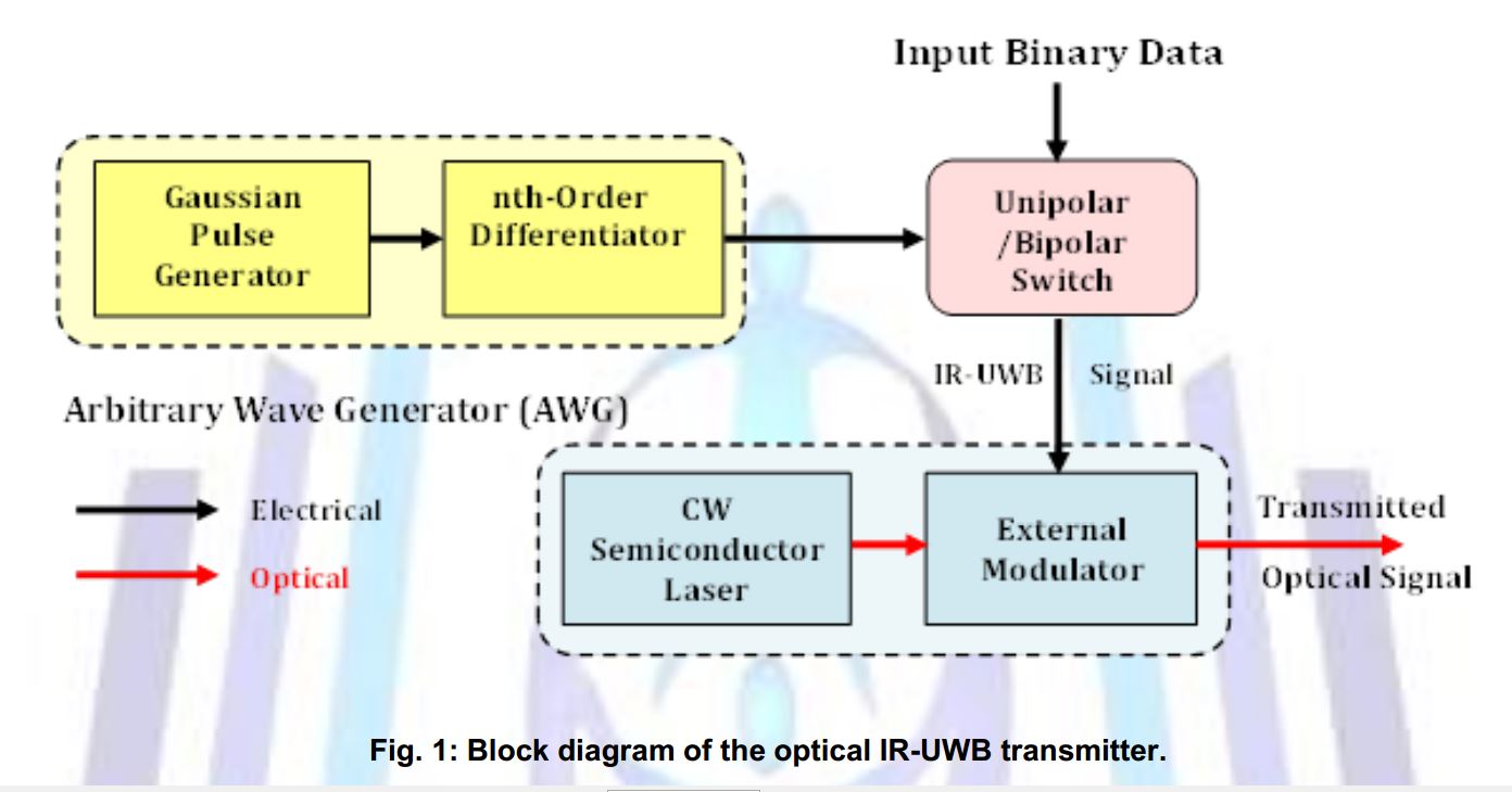
Jaffer i couldn’t resolve above issue (might be due to having Opti sys V-7) and now I started working on your paper name “Transmission Performance Investigation of IR-UWB Signals over Existing optical fiber Transmission link “.
1. I want to know what component u have used as “High speed Uni-polar switch (Electrical)” for modulation of Binary Data ?? as there is no such component available in Opti Sys V-7 libarary. I am attaching fig from ur paper as follow.
2. What type of digital data format u have used in ur paper ? NRZ or RZ ?
I will be thankfull to u.
Best Regards
Attachments:
Thanks Damian Marek.
Best Regards
Dear Jaffer,
in paper author worked in real world but i am working on simulator that’s why i used Gaussian source instead of mode lock laser.
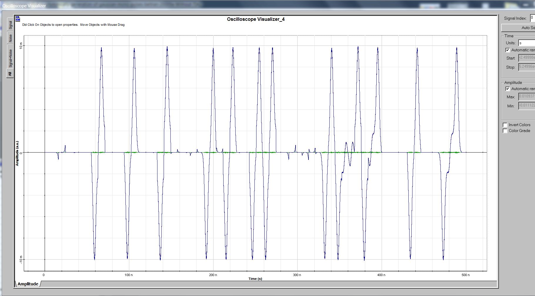
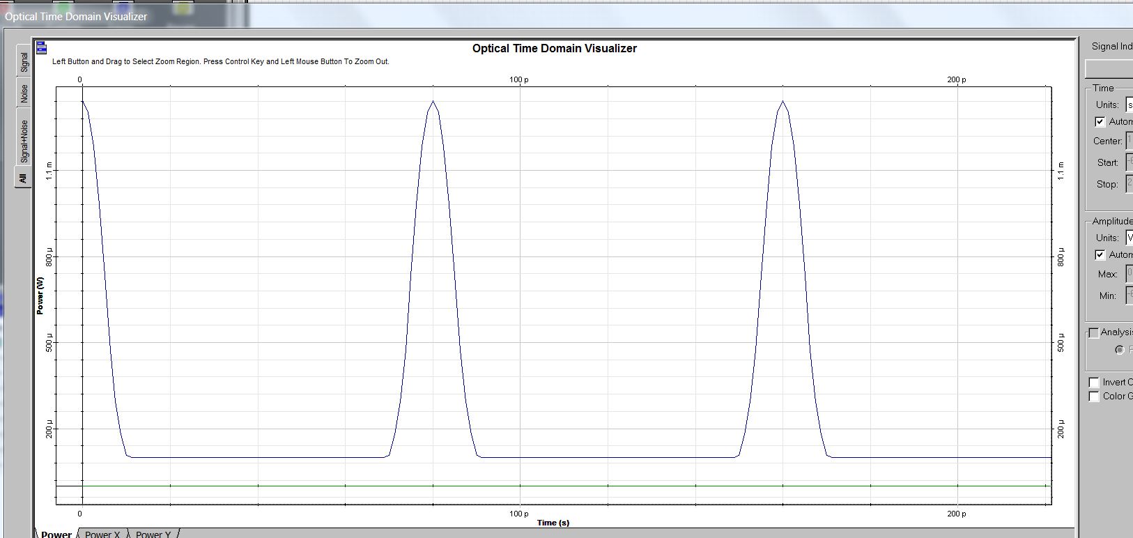
Jaffer as i have gotten Gaussian mono cycle pulses after photo detection which u can verify from graph attached above but the problem i am facing in my opinion is in BER analyzer because my BER is unable to give me results i.e. single Eye diagram.
So, I don’t know what setting should i apply in BER analyzer to get single Eye diagram ?
In your paper jaffer have u changed any setting at BER analyzer ?? or just connected BER analyzer with other components to find BER and eye diagram using default settings ?
Regards
Dimian,
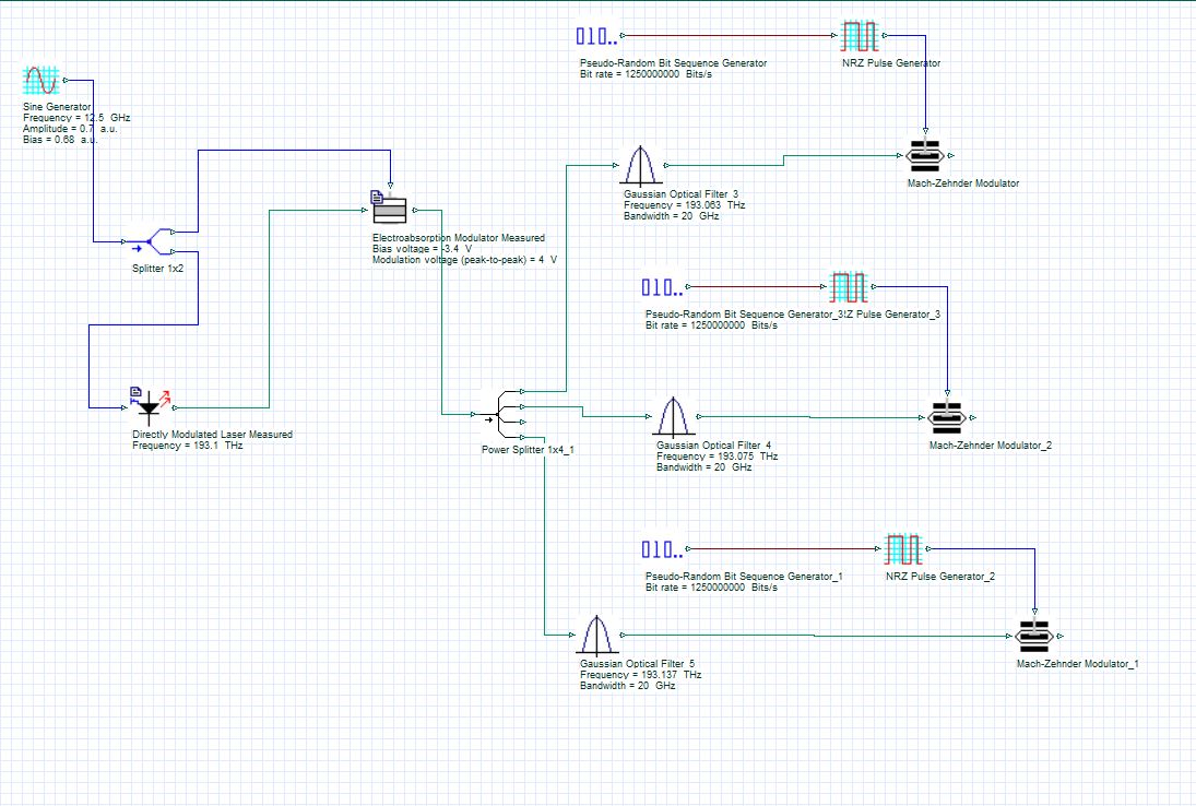
If i keep Global bit rate = 12.5 G Bit/sec, use RZ instaed of NRZ because it has twice bandwidth and keep Bit rate = 1.25Gbit/sec at Pseudo Randon bit Generator, then still its ok ?? Or i should change any parameter ??
I am using samples per bit = 64 or above for this setup ??
Is this still ok or i need any modification ?
I am attaching pic of scenario below (consider RZ instead of NRZ)
Best Regards
Attachments:
Thanks ALot Damian, u clear my ambiguities.
Best Regards
ok thanks alot Jaffar,
i will wait for ur response.
Best Regards
Thanks a lot Jaffar for your kind participation,
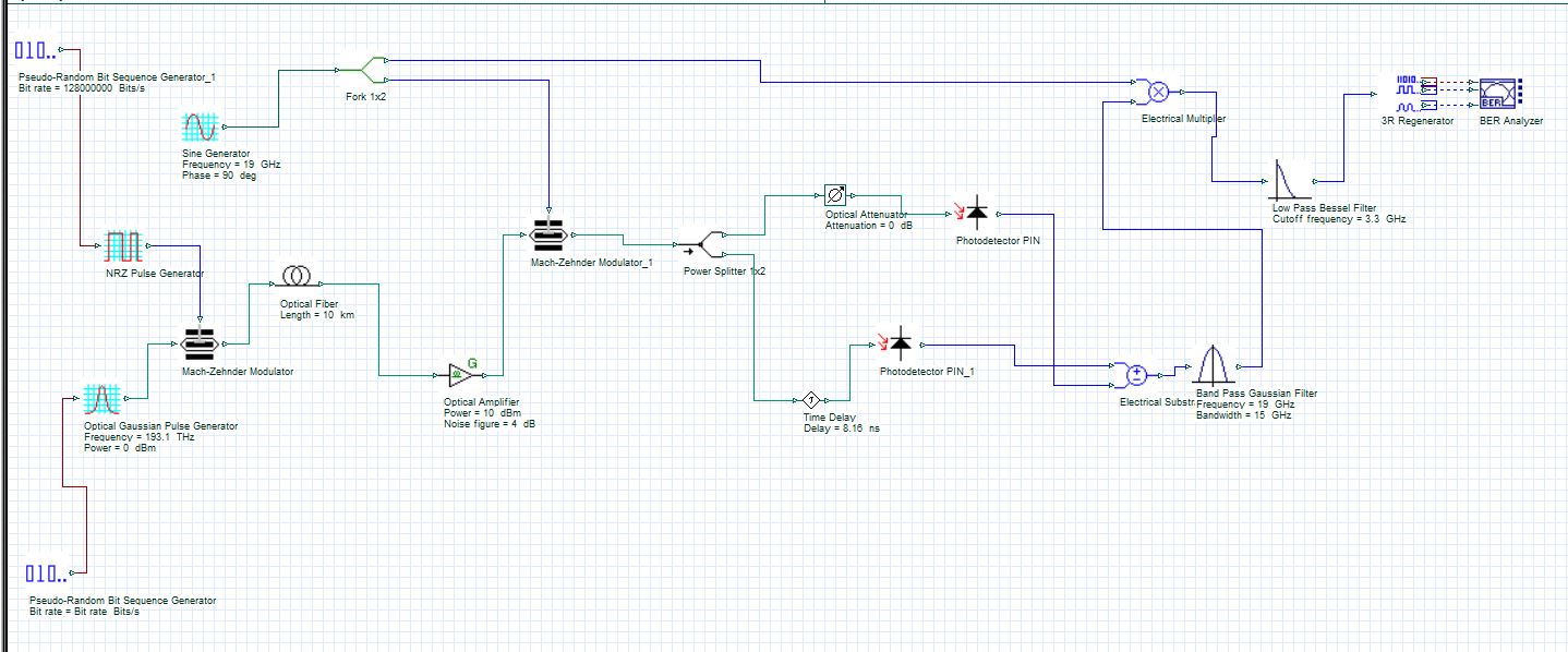
I am attaching picture of my setup and also the paper which I am simulating (the setup diagram is at page 4 of research paper), u can check them in below attachment.
Kindly comment where I am getting wrong so that I beocome able to find BER and eye diagram, because still I have not found any solution to this problem.
I have saved your paper but did not studied due to difference in working domain but now I will study them, to get an idea of how u have done calculation of BER and eye diagram in Opti sys for mono and duplet pulses.
I don’t know why your upper shared link is not working, kindly email me your paper at engr.bilalaziz@gmail.com.
Best Regards
Thanks a lot Ravil !
Yes my modulated signal has DC component and I want to remove it but could not find any way to get rid of it.
If it would be an electrical signal than I can use clipper/ clamper to remove Dc component but I don’t know how to remove Dc component in Optical signal.
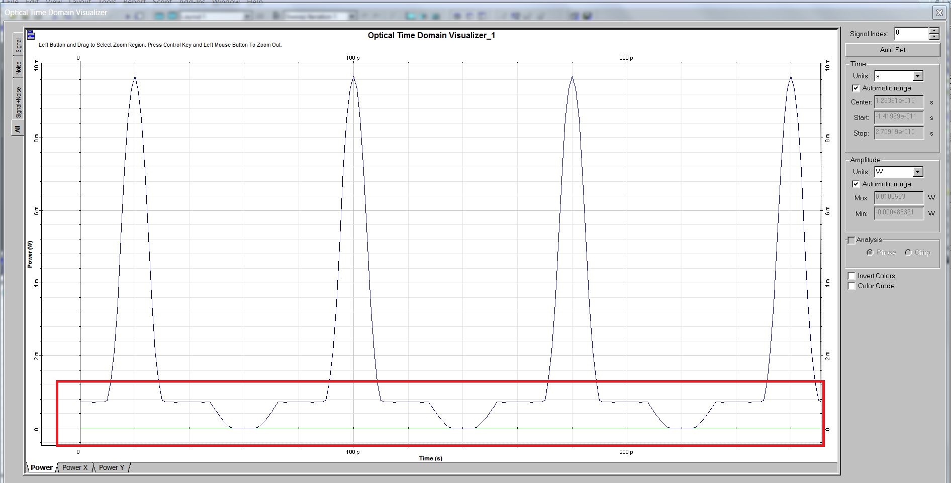
Dear Ravil after modulation from EAM, I am going to contract this signal but due to DC component I am getting a contracted modulated signal like shown in below attached pic.
If I would transmit such a signal over fiber it will degrade my sys overall performance severely due to collision( as u can see from red portion in graph) and many other factors.
So to get better performance I have to get rid of this DC component. I hope u get my point.
If anyone has solution to this problem kindly share.
Best Regards
Attachments:
Thanks a lot Dear Jaffar for your kind response,
1. I am working in Uni-phase modulation format and u can verify it from the signal graph attached above (I am also attaching it below).
That’s the problem I don’t know why i am still getting two eye diagram ?
2. I’m using NRZ pulse generator and always work in On Off keying format (I am attaching project file where u can verify it)
Further, just for verification, Can u tell me how can I set On off keying in Opti sys 7 because there is no option about OOK modulation format in my setup.
3. As I could not get any solution to this problem so I decided to transmit only “Gaussian pulses” in UWB over fiber transmission instead of “Gaussian mono cycle pulse”, Is this right or wrong decision ?
4. I am searching different references where they have used Gaussian pulses in UWB over fiber transmission but could not find any good reference from reputable confreres/ journals like JLT, OFC etc.
Have u notice any work/research paper/ journal which had used Gaussian pulses in UWBoF transmission ?? kindly share it.
i am thankful to you for ur participation at post.
Best Regards
thanks Alot Jaffar !
i have made many calculations my minimizing laser power but response is still similar i.e. the modulated signal never started from zero.
Only thing that happens by minimizing laser power is that the modulated signal start him self from lower values in same proportion as i am minimizing laser power.
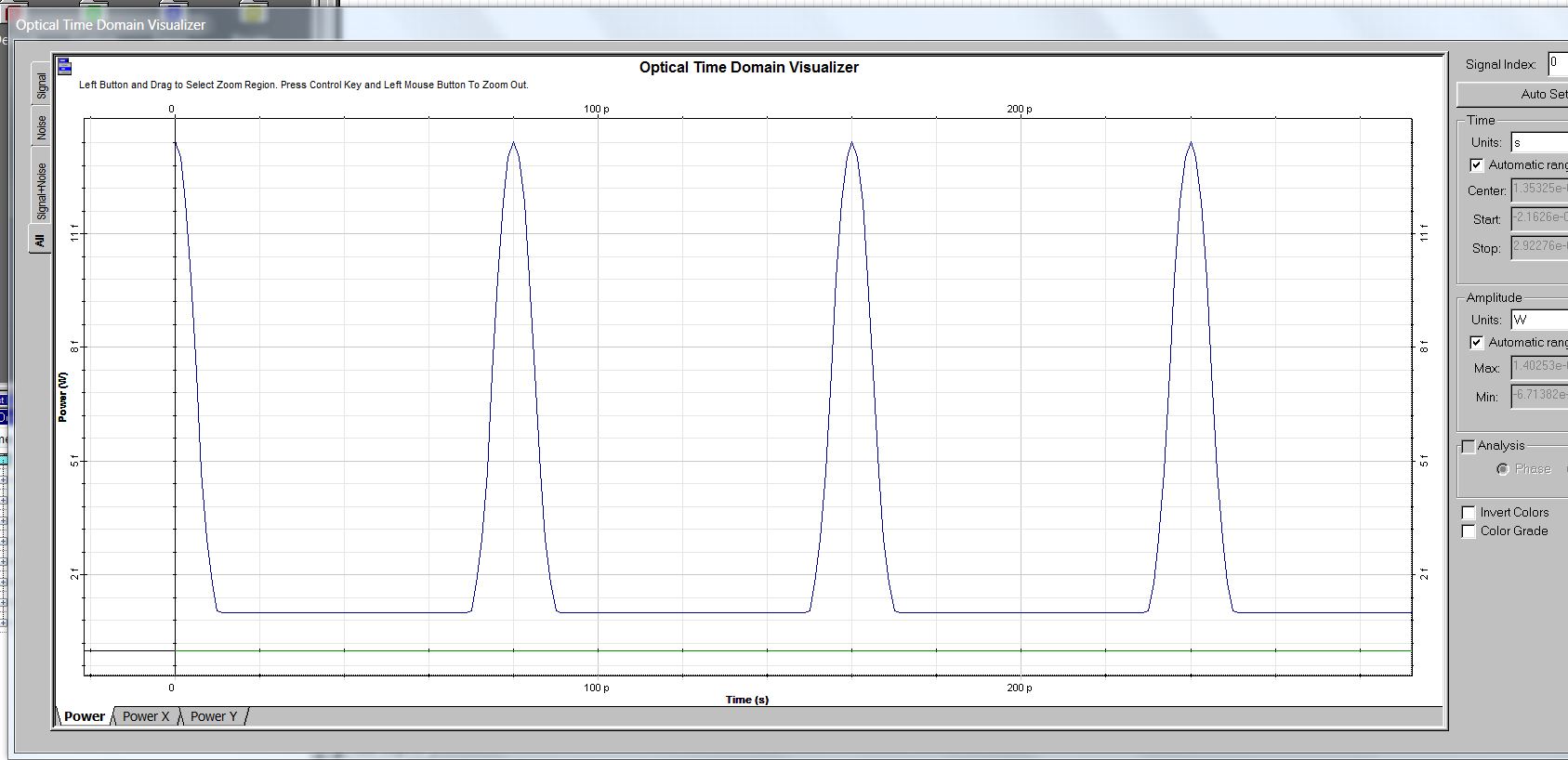
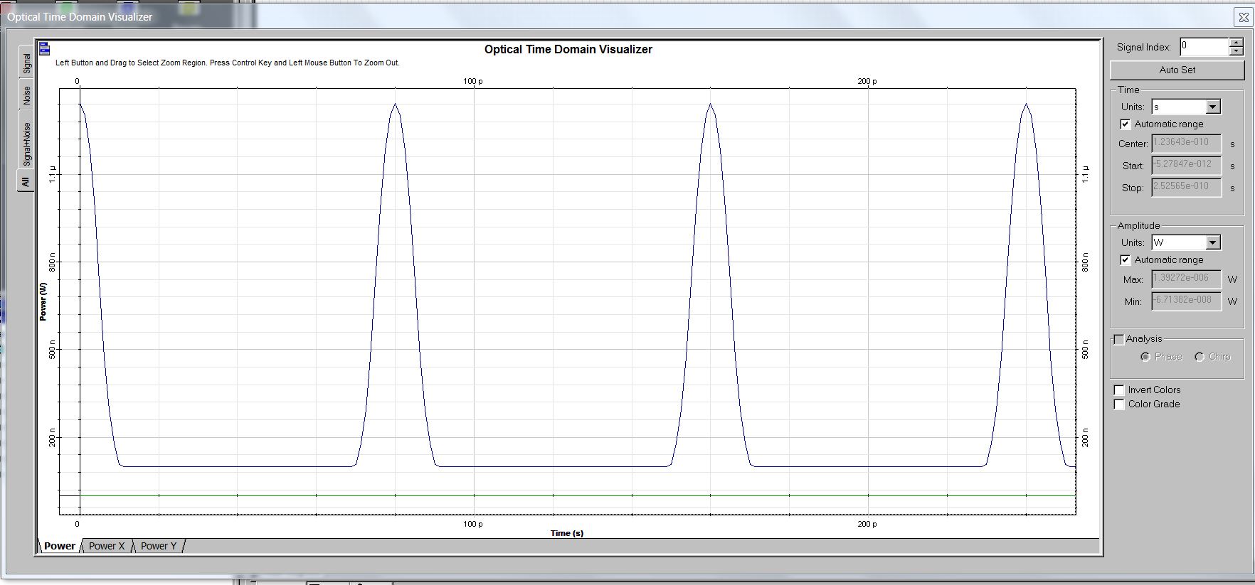
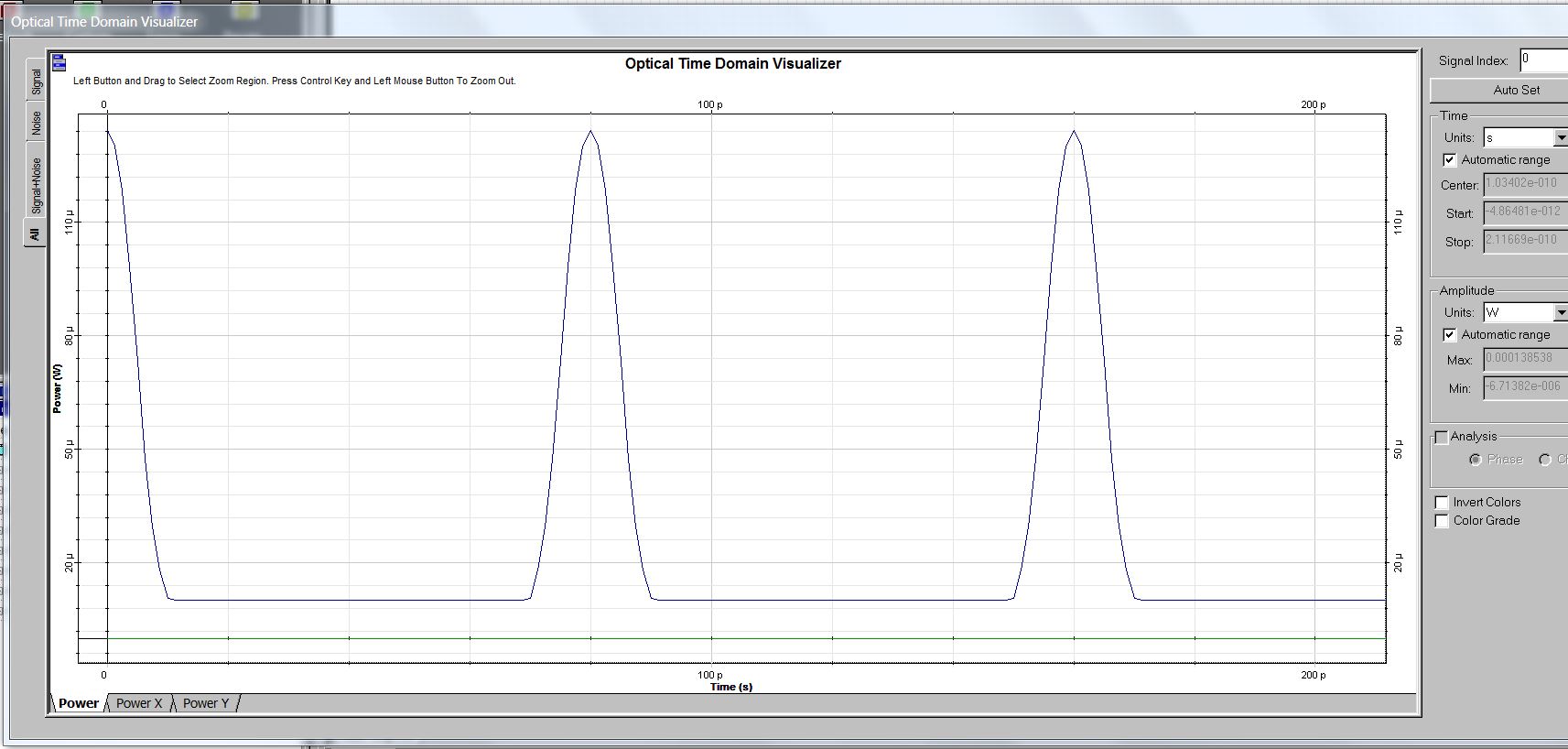
I am attaching some the graphs of modulated signal at different laser powers
fig A with laser power = -100 dBm
fig B with laser power = -20 dBm
fig C with laser power = 0 dBm
fig D with laser power = 10 dBm
Basically i want modulated signal to start from level zero without changing laser power (because minimizing my laser power will degrade my system performance very badly) .
So there is any way to get modulated signal from level zero is by using any procedure/technique on EAM. So any one know any technique on EAM to get required signal kindly share.
OR
if any one has any clue regarding this problem kindly share.
Best Regards
Attachments:
Thanks Alot Damian for your kind response !
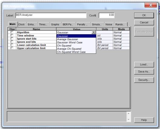
But there is no such option like “Measured” over there. I am sharing in below pic all options which i get after scrolling down. kindly tell me how can i use measured value in BER analyzer.
Regards
Attachments:
Ajay if u want to save opti sys 13 file in Opti sys 7 then it is not possible and even u can’t open file of Opti sys 13 in Opti sys 7.
As for as Opti sys 13 and 7 are concern they are not backward compatible but i don’t know about other versions of opti sys.
I hope u get a point.
Regards
Thanks alot Ajay.
i got the figures and i am also sharing the link for other forum members so that they could get benefit from it.
link
http://www.roithner-laser.com/index.html
Regards