This lesson demonstrates the application of traveling wave SOA as a wavelength converter using the four-wave mixing effect.
Four-wave mixing (FWM) is a nonlinear effect that takes place when two waves (signal and pump) at different wavelengths are injected into an SOA. A third optical field is generated at the device output, with frequency Wc = 2Wp – Ws = Wp – Ω , where Wp and Ws are the frequencies of the pump and signal field respectively, and Ω = Ws – Wp is detuning between signal and pump.
Several physical phenomena can generate FWM in SOA. When detuning at the order of several GHz, the main mechanism is the carrier density pulsation induced by the signal-pump beating. The carrier density pulsation appears because of the stimulated emission. Our SOA component can handle generation mechanism of FWM. For higher values of detuning, carrier pulsation is no longer effective, and FWM is created from two fast intraband relaxation processes:
- spectral hole burning
- carrier heating
As their characteristic times are of the order of hundreds of femtoseconds, they become important for values of detuning greater than 1THz [2] and [3].
The main advantage of frequency conversion based on FWM is independence of the modulation format and the bit rate. An additional advantage of this technique is the inversion of the signal spectrum and the resulting reversal of the frequency chirp. This property can be used to achieve dispersion compensation. The main disadvantage of the FWM converter is its low conversion efficiency [2] and [3].
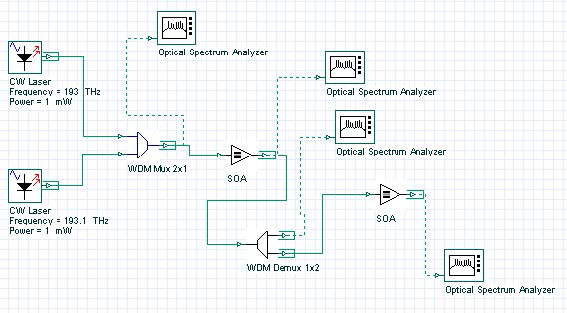
To realize this idea, two CW signals are multiplexed and then launched into SOA, as shown in Figure 1.
Figure 1: Two multiplexed CW signals
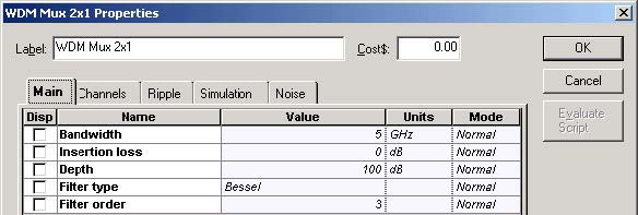
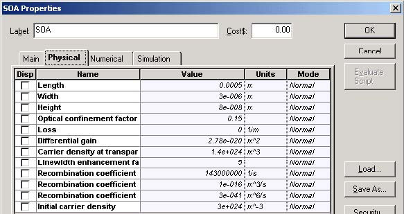
Using this project, we will demonstrate the principle of carrier density pulsation induced FWM in SOA. To demonstrate this, two CW signals with carrier frequencies 193 and 193.1 THz and the power of 1 mW (without line widths, initial phases, and polarizations) are multiplexed with the help of WDM Mux 2×1 and launched in SOA. Figure 2, Figure 3, and Figure 4 show the WDM and SOA parameters.
Figure 2: WDM Mux 2×1 Main parameters
Figure 3: WDM Mux 2×1 channels
Figure 4: SOA Physical parameters
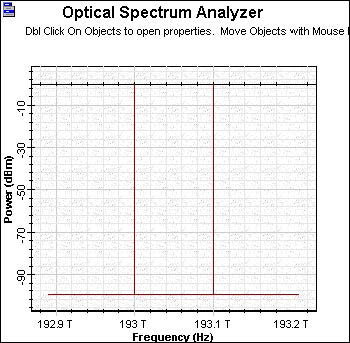
Figure 5 shows signal power after the WDM Mux 2×1.
Figure 5: Signal power after the WDM Mux 2×1
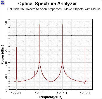
Figure 6 shows the signal power after the first SOA.
Figure 6: Signal power after the first SOA
In Figure 6, we can see the power generated from the new FWM frequencies at 192.9 THz and 193.2 THz respectively. With the following demultiplexer, we separate the frequencies into 193.1 THz and 193.2 THz. The demultiplexer Channels parameters have been changed (see Figure 7).
Figure 7: WDM Demux 1×2 channels
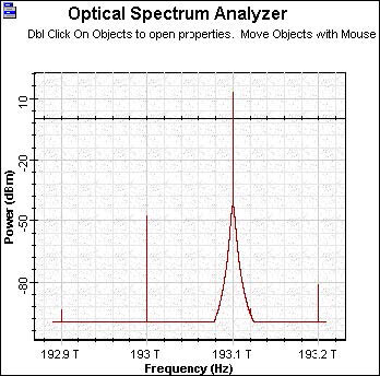
Figure 8 shows the spectrum in the channel at 193.1 THz after demultiplexing.
Figure 8: Channel spectra at 193.1 THz after demultiplexing
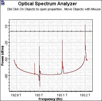
To obtain a better signal from the FWM at 193.2 THz after demultiplexing, we amplify the signal with the second SOA with the same properties as the first one. Figure 9 shows the resulting spectrum.
Figure 9: Improved signal from the FWM at 193.2 THz after demultiplexing
The result of the second amplification FWM generated signal at 193.2 THz with power comparable with the result of the initial CW signal at 193.1 THz is obtained.
This lesson demonstrated the principal possibility of application of traveling wave SOA as a wavelength converter using four-wave mixing.
References:
[1] Terji Durhuus, Benny Mikkelsen, Carsten Joergensen, Soergen Danielsen, and Kristian Stunkjaer, “All-optical wavelength conversion by semiconductor optical amplifier”, Journal of Lightwave Technology, Vol. 14, pp. 942-954,1996.
[2] G.P. Agrawal, “Fiber Optic Communication Systems”, 2nd Edition, John Wiley & Sons Inc., 1997.
[3] R.Sabella and P.Ludgi, “High speed optical communications”, Kluwer Academic Publishers, 1999.


