
OptiSPICE allows for the design and simulation of optical and electrical circuits at the transistor level, from laser drivers to trans-impedance amplifiers, optical interconnects, and electronic equalizers. This software’s waveform analysis capabilities make it a cornerstone of modern photonics.
With the imminent coexistence of electrical and optical components at the chip and board level, it is important to provide designers with a reliable simulation framework that can accurately and efficiently predict signal behavior in optoelectronic integrated components.
OptiSPICE produces self-consistent solutions for optoelectronic circuits that contain feedback spanning both optical and electrical parts. It is a fully integrated solution for parameter extraction, schematic capture, circuit simulation, and waveform analysis.
BENEFITS
- Significantly reduce product development costs and boost productivity using OptiSPICE’s comprehensive design environment to simulate optical and electrical circuits in one simulation engine.
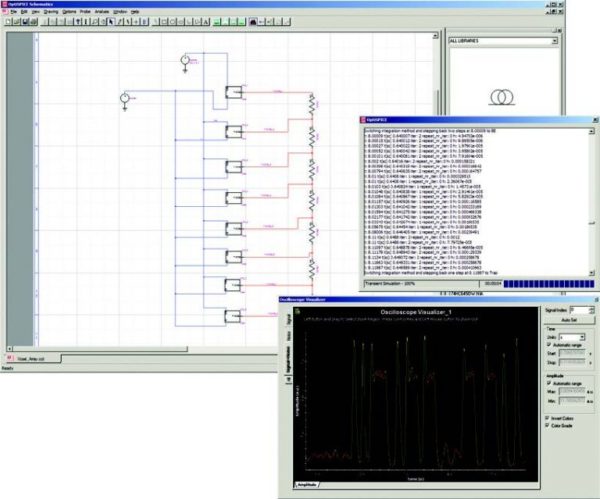
- Run state-of-the-art transient time domain, small-signal frequency, and noise analysis to accurately predict the behavior of advanced circuits.
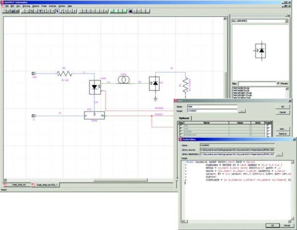
- OptiSPICE Schematics offers direct schematic entry in an intuitive graphical user interface. It facilitates schematic capture, parameter specification, waveform probing, and usage.
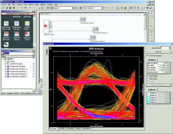
- Post-simulation waveform analysis of optoelectronic circuits using OptiSPICE Waveform Viewer or OptiSystem’s advanced visualization tools (OSA, eye diagrams, oscilloscopes).
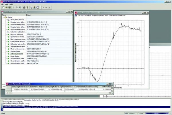
- Includes parameter extraction tools for OptiSPICE model creation. From measurement data, parameter extractors are used to find the best set of OptiSPICE model parameters to fit the measurement.
APPLICATIONS
- Design and simulation of optical and electrical circuits at the transistor level, from laser drivers to trans-impedance amplifiers, optical interconnects, and electronic equalizers.
- Use software-based waveform analysis to monitor and optimize the performance of signals in telecommunication and other industries.
- Signal integrity analysis of optoelectronic circuits, including eye diagram analysis with BER patterns.
Learn more about OptiSPICE’s applications here.
Schematic Editor
- Integrated Device Symbol Editor allows you to create custom symbols for devices or hierarchical blocks using standard drawing tools.
- Hierarchical Design with unlimited levels is fully supported. Any symbol on a schematic can contain another schematic of arbitrary size. Blocks can be nested to any desired depth. Any number of hierarchical blocks can be opened for editing at any time.
- OptiSPICE Schematics includes a powerful Custom Report Generator tool for netlist and text report generation. The report format is driven by a “form file,” which contains formatting commands and constant text. Form file features allow you to control: the overall report structure, e.g., netlist formats by signal or by device, and listings by device for a bill of materials.
- In addition to optoelectronic circuit simulation tools, OptiSPICE includes several powerful technologies for scripting and customization that allow full access to all design data and virtually every program function.
- The schematic editor can save diagrams in the standard PDF (Acrobat), WMF (Windows Metafile), and DXF (AutoCAD) graphics formats. This capability allows you to pass graphics to other programs for plotting, enhancement, or incorporation into other documentation.
- Generate OptiSPICE or HSPICE-compatible netlists.
Simulator
- Along with being a waveform analysis software, the OptiSPICE simulator incorporates equations governing optical components directly into an electrical simulation framework, thus forming single-engine optoelectronic simulation software.
- Includes thermal macro models that model the thermal behavior of devices. Users can incorporate them into the optoelectronic circuit simulation to provide reliable simulation results.
- Supports a wide variety of electrical circuit elements such as diodes, transistors, BJTs, and MOSFETS, and optical components such as laser diodes, optical fibers, and photodiodes.
- Able to handle integrated optics, multiple optical channels (WDM), and multimode signals.
- Advanced numerical techniques for superior convergence. Advanced solver automatically selects the best convergence algorithm for reliable transient simulation convergence.
- Active and passive device model compatibility with industry HSPICE standards. Users can easily import external models and netlists written in HSPICE format to OptiSPICE.
- Enables accurate optoelectronic circuit simulations by supporting BSIM3 models.
- Provides an accurate implementation of different frequency-dependent models, including S-parameters, pole/residue expressions, and transmission line models.
Waveform Analysis
- OptiSPICE Waveform Viewer is a post-simulation waveform analysis software tool that allows designers to view the optical and electrical signal data captured from any probe placed in an OptiSPICE circuit design.
- 2D visualization capabilities include bidirectional (time-domain) analysis of currents, voltages, optical power, magnitude, and phase measurements.
- A button-activated control allows designers to automatically import the same probe data into OptiSystem’s advanced post-processing environment for further analysis of optoelectronic circuits (including eye diagram and optical spectrum visualization, BER, and Q factor measurements).
Parameter Extraction
- A laser parameter extractor allows users to generate models by extracting and fitting parameters from static and dynamic measurements of lasers.
- Filter parameter extractor allows users to translate S-parameters into compact and efficient pole/residue representations.
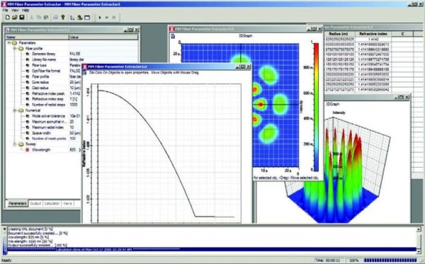
- Multimode fiber parameter extractor includes an optical fiber mode solver that allows users to generate libraries of fibers from a user-defined refractive index profile.
Learn more about software-based waveform analysis and optoelectronic circuit simulation with our detailed OptiSPICE manuals.