This lesson demonstrates the application of traveling wave SOA as a wavelength converter using cross-gain saturation effect.
The principle use of the cross-gain modulation in SOA is as an intensity-modulated input signal that modulates the gain in the SOA via gain saturation effect. A continuous wave signal at the selected output wavelength is modulated by the gain variation. After the SOA, the continuous wave signal carries the same information as the intensity modulated signal. The input signal and the CW signal can be launched either co-directionally or counter-directionally into the SOA. A co-propagation scheme is considered here.
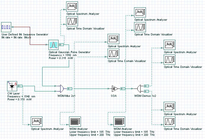
To realize this idea, the intensity-modulated input signal and a CW signal are multiplexed and then launched into SOA, as shown in Figure 1.
Figure 1: Multiplexed intensity-modulated input signal and CW signal
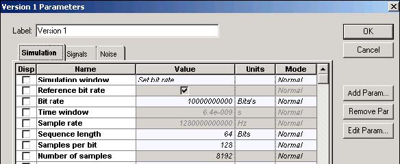
To demonstrate conversion at 10 Gb/s requires following global parameters (see Figure 2).
Figure 2: Simulation parameters
The intensity-modulated input signal and a CW signal have carrier wavelengths of 1550 and 1540 nm (or frequency separation from 1.25 GHz) and powers of 0.316 mW and 0.158 mW (without line widths, initial phases, and polarizations). The signals are multiplexed with the help of WDM Mux 2×1 and launched in SOA.
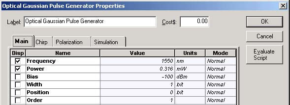
Figure 3 shows the Optical Gaussian Pulse Generator parameters.
Figure 3: Optical Gaussian Pulse Generator Main parameters
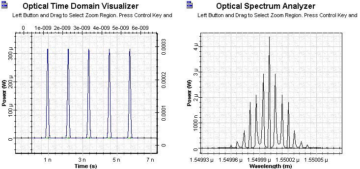
Figure 4 shows the shape and spectrum of the intensity modulated signal.
Figure 4: Shape and spectrum of the intensity modulated signal
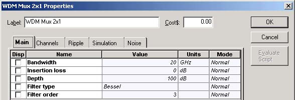
Figure 5 shows the multiplexer parameters and channels.
Figure 5: WDM Mux 2×1 Main parameters and channels
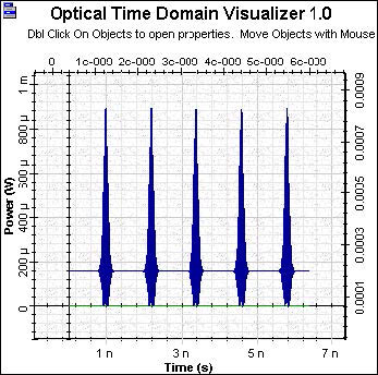
Figure 6 shows the shape of the WDM Mux 2×1 signal after multiplexing.
Figure 6: Shape of WDM Mux signal
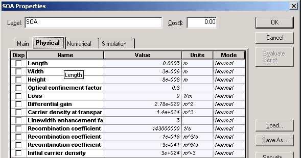
Figure 7 shows the SOA Physical parameters.
Figure 7: SOA Physical parameters
These amplifier parameters give the unsaturated single pass gain G0 ~ 30 dB.
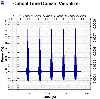
Figure 8 shows the form of the amplified signal.
Figure 8: Amplified signal
The amplified signal passed through the demultiplexer, which has properties similar to the multiplexer. Figure 9 shows the signal shape and spectrum at λ = 1550 nm after the demultiplexer.
Figure 9: Shape and spectrum of the signal at λ = 1550 nm
Figure 10 shows the signal shape and spectrum at λ =1540 nm after the demultiplexer.
Figure 10: Shape and spectrum of the signal at λ = 1540 nm
The inversion of the signal can be clearly seen.
This lesson demonstrated the application of traveling wave SOA as a wavelength converter using cross-gain saturation effect.
References:
[1] Terji Durhuus, Benny Mikkelsen, Carsten Joergensen, Soergen Danielsen, and Kristian Stunkjaer, “All-optical wavelength conversion by semiconductor optical amplifier”, Journal of Lightwave Technology, Vol. 14, pp. 942-954,1996.
[2] G.P. Agrawal, “Fiber Optic Communication Systems”, 2nd Edition, John Wiley & Sons Inc., 1997.
[3] R. Sabella and P. Ludgi, “High speed optical communications”, Kluwer Academic Publishers, 1999.


