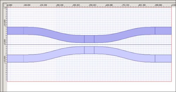
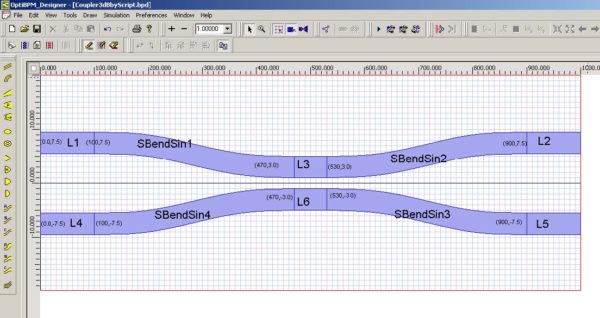
To draw and position the waveguides, perform the following procedure (see Figure 8).
| Step | Action |
| 1 | Adjust the zoom to fill the screen. |
| 2 | To snap to the grid and to the waveguide:
a. From the Preferences menu, select Layout Options. The Layout Properties dialog box appears. b. Under Grid, select the Snap to Grid and Snap to Waveguide check boxes. c. To save the settings and return to the layout, click OK. |
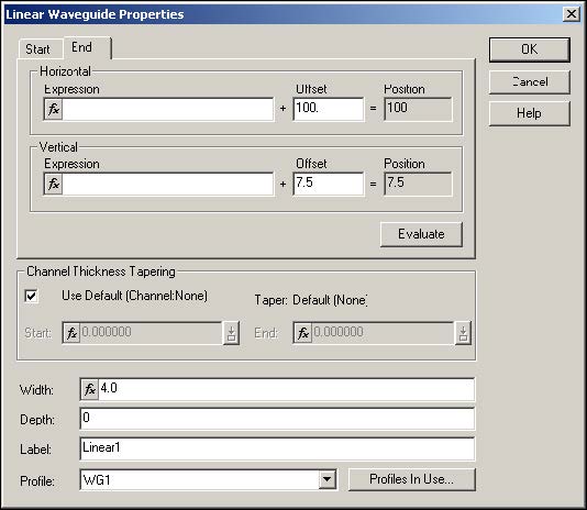
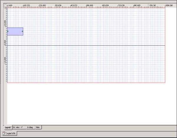
| 3 | Draw and edit the linear waveguide (see Figure 8).
a. Start offset: Horizontal: 0 Vertical: 7.5 b. End offset: Horizontal: 100 Vertical: 7.5 |
Figure 7: Linear Waveguide Properties dialog box
Figure 8: Drawing the linear waveguide
| 4 | To apply the settings, click OK. |
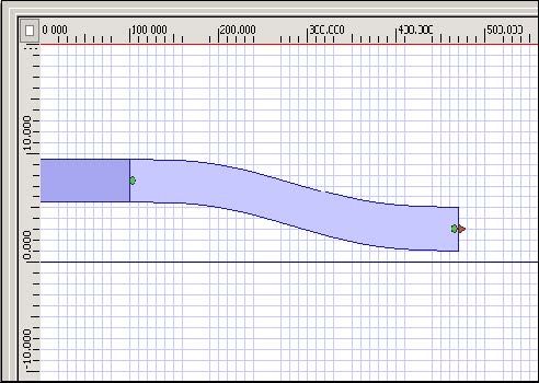
| 5 | Draw and edit an S-Bend Sine Waveguide (see Figure 9).
a. Start offset: Horizontal: 100 Vertical: 7.5 b. End offset: Horizontal: 470 Vertical: 3 |
Figure 9: Drawing the S-Bend Arc Waveguide
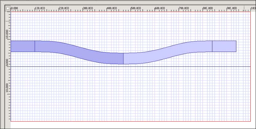
| 6 | To create a mirror image of the waveguides, press Ctrl, click both waveguides to select them, and click the Mirror to Right button on the Flip and Mirror toolbar.
OR Press Ctrl, click both waveguides to select them, and select Edit > Flip and Mirror > Mirror to Right (see Figure 10). |
Figure 10: Creating a mirror image of the waveguides
| 7 | Deselect all waveguides and press Ctrl to select the two waveguides on the right (see Figure 11). |
Figure 11: Selecting the waveguides
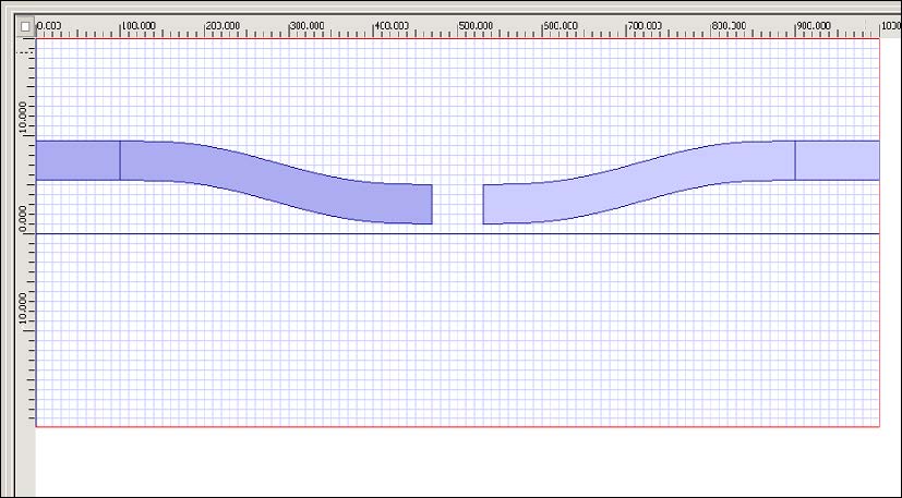
| 8 | Click and drag the two waveguides so they line up with the right boundary of the calculation window (see Figure 12). |
Figure 12: Moving the selected waveguides
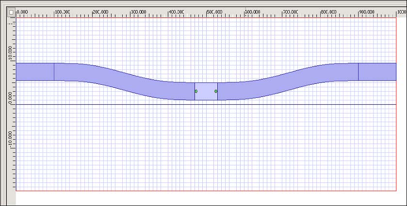
| 9 | Draw a linear waveguide between the two S-Bend Arc waveguides (see Figure 13). |
Figure 13: Filling in the gap
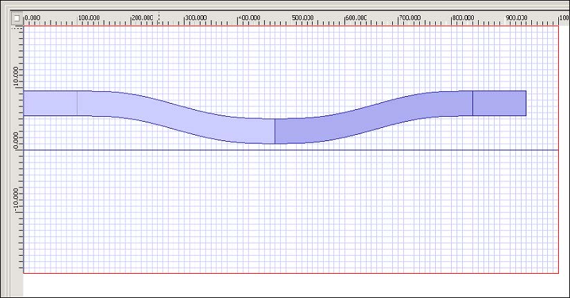
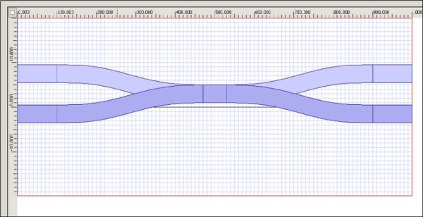
| 10 | To create a mirror image, select all the waveguides, and click the Mirror to Bottom button on the Flip and Mirror toolbar (see Figure 14).
OR Select all the waveguides, and select Edit > Flip and Mirror > Mirror to Bottom (see Figure 14). |
Figure 14: Creating a mirror image of the waveguides
| 11 | Select all the bottom waveguides drag the waveguides down. Centre them so the design is symmetric (see Figure 15). The waveguide placement is complete. |
Figure 15: Positioning the mirrored waveguides
| 12 | Verify each waveguide and check that the co-ordinates are correct (see Figure 16).
Note: If necessary, change the co-ordinates in the Waveguide Properties dialog box. |
Figure 16: Waveguide co-ordinates


