Base
| Full Name | Joshua Donald |
| Job Title | Photonics Applications Engineer |
| Country |
Forum Replies Created
Hi Jagan,
A similar question was asked before.
You can see the answer here https://optiwave.com/forums/topic/validation/
Regards,
Josh
Hi Francisco,
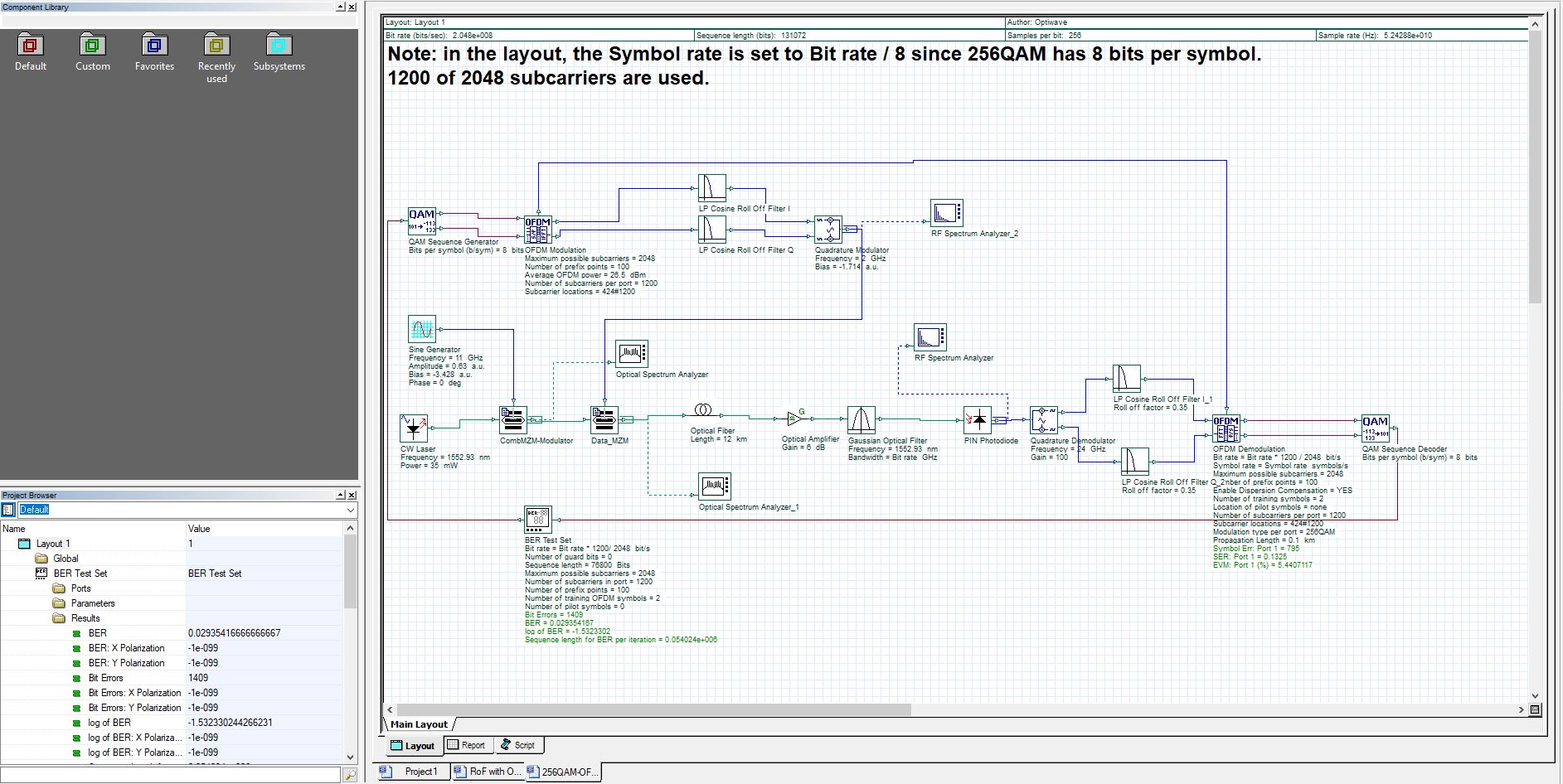
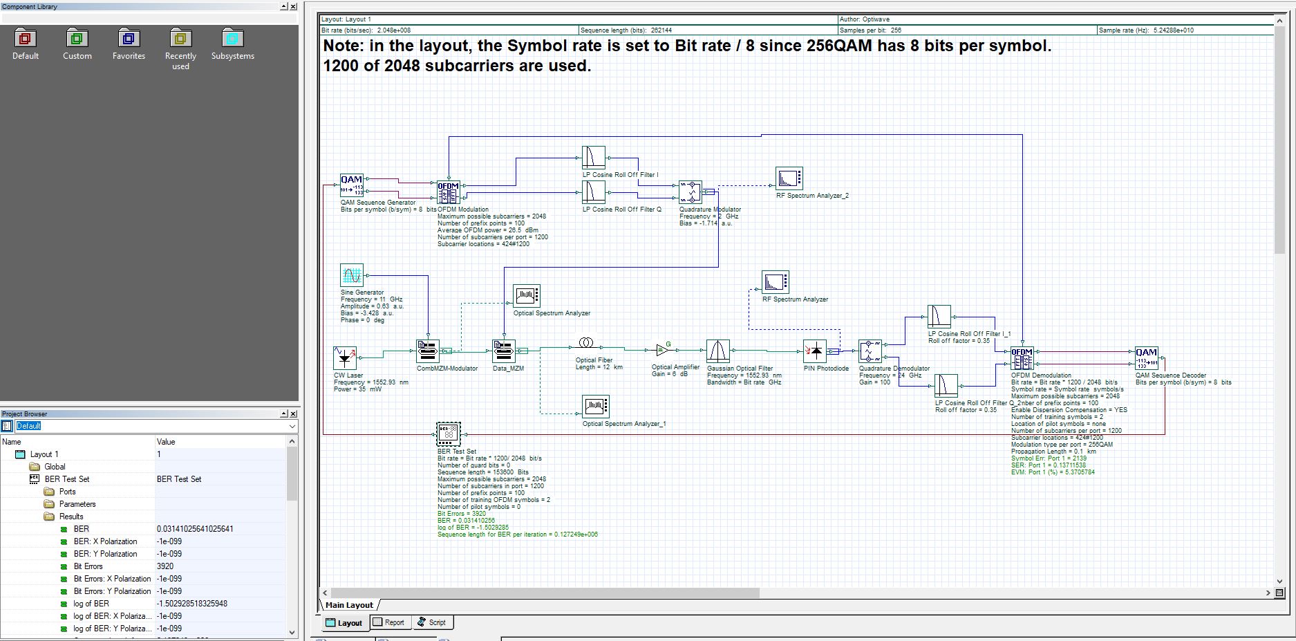
Since Bit error rate is the number of bit errors divided by the total number of transmitted bits that means BER is a ratio. Because of this we should not expect a different BER rate to come as a result of changing the sequence length. In general, changing your sequence length or making it longer will not change your BER if there is enough bits transmitted to characterize the system. Advanced modulation schemes requires long sequence lengths. If you do use short sequence length will get different results every time. However, when you use suitable length, the results will not change beyond that length.
I’ve attached 2 pics of the same system with the sequence lengths doubled in the second pic, the BER however remains more or less the same. (some variance due to random noise etc). To measure if your BER is 10^-9 or lower just run the project and the BER will be visible in the project browser. If you need a BER rate of 10^-9 or lower you will have to change other parameters and settings, but sequence length should not influence BER.
Best,
Josh
Yes it can be connected, here is a picture below. There are also so fbg examples in the example library. To see them just click file, examples and search fbg
Attachments:
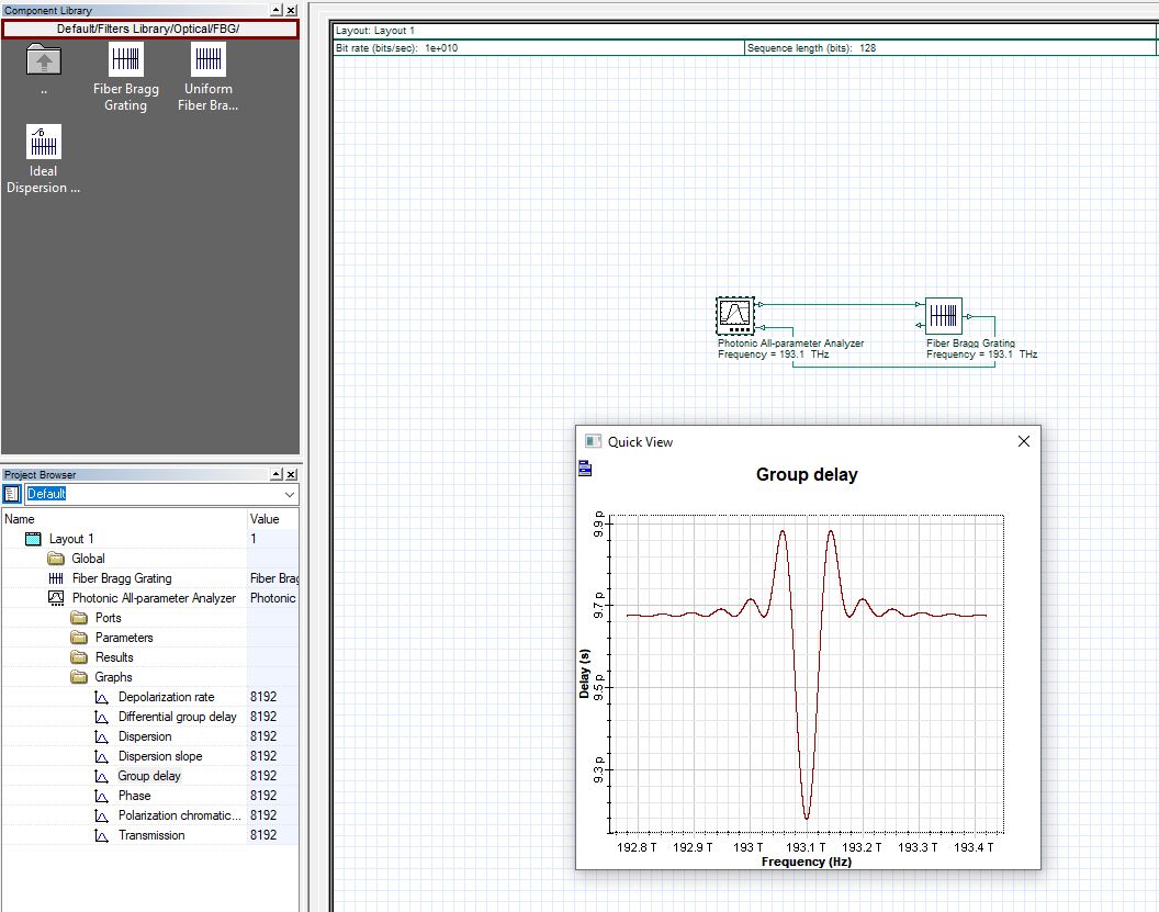
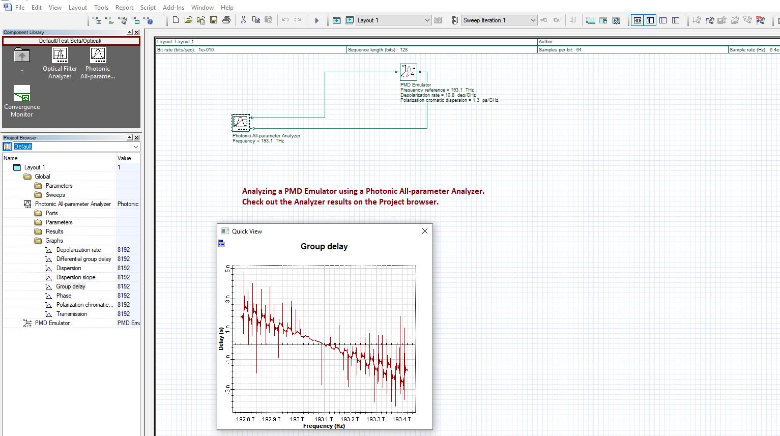
Hi Rajkumar,
I attached a picture of an example below. Once you have the photonic all-parameter analyzer attached to whatever you wish to analyse, you can click “view” and then click “project browser” and the project browser should popup below your component library. you can then expand the photonic all parameter analyzer and you will see various sub folders. if you wish to see graphs expand the graphs folder and double click on the graph to view it.
Best,
Josh
Attachments:
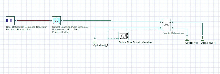
Hi Yu,
Would you be able to elaborate on what you mean by wanting to create a file like structure?
For the diagram you provided I would consider using a bidirectional coupler since you require a coupler with 3 outputs. The setting for either component can be seen by double clicking the component. If you know what frequency is required you can put that value into the frequency value of the optical Gaussian pulse generator. So for example if you are modelling a lidar sensor you might choose a frequency of 193thz or 316thz. If you chose the coupler to be wavelength dependent you should adjust the wavelength of the coupler according to the frequency of the pulse selected.
Best,
Josh
Attachments:
Hi Amrita,
Would you be able to attach the project in a .zip file please so that we can see it. Osd files are not able to be uploaded for security reasons.
Best,
Josh
Hi Prakasha,
there are some examples that use oscillators in our example library. go to file , examples and under component sample files/receivers library/regenerators you can find a voltage controlled oscillator example. you can also check for other systems containing oscillators in Advanced modulation systems or maybe Lightwave systems. You can also check out the optisystem manuals to see if there is anything there that might be of use for you https://optiwave.com/resources/applications-resources/lightwave-system-components/. all of the manuals available are displayed at the right of the page.
Best,
Josh
under default/amplifiers library/optical you can find the edfa amplifier. you will have to adjust the various properties to acheive a gain of 10db. If you press help you will find the equations that you will need to use. Solving Equation 1, Equation 2, and Equation 3 under stationary conditions allows you to determine the amplifier performance features. to make it simpler you can also use the edfa black box. the edfa black box allows you to simply choose the value of gain, power, etc instead of having to perform the calculations that would be required if you used the edfa.
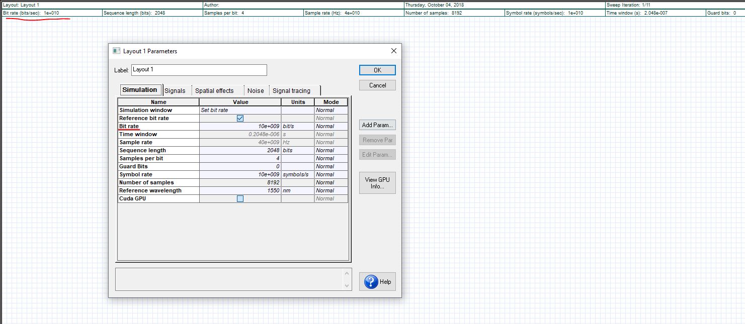
Hi Abdikarim,
The effects of noise are present in various components like the optical fiber and amplifier. Because the noise has an element of randomness to it, that will cause some variation in your Q factor every time you simulate. As for checking the bit rate you can double click an empty area in the work-space and the layout parameters window will open up. In the layout parameters you can find and edit bit rate.
Best,
Josh
Attachments:
Hi Usama,
I’ll have a look at this and get back to you.
Regards,
Josh
Hi Mohmmed,
At what point are you encountering problems, and are there any specific error messages you are receiving? Would you be able to send a screenshot?
Regards,
Josh
Hi Emrah,
I noticed there is no optical null at the unused input of the reflector bidirectional. You can try adding an optical null there because any input that is unused needs a null connected for the project to calculate. If that does not work you can send the project in a zip file to my email joshua.donald@optiwave.com for me to have a look at it.
Regards,
Josh
Attachments:

Hi Emrah,
Can you try sending the screenshot again, it did not properly attach.
Regards,
Josh
Hi Mohammad,
Were you using a paid version of Optisystem or were you using the free trial.
Regards,
Josh
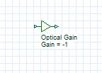
Hi Adnan,
In the Component library under Default/Signal processing library/Arithmetic/Optical/ there is the optical gain component. You can change the gain to -1 to act as an optical not. This may solve your problem.
Regards,
Josh