
Base
| Full Name | davcm |
| Organization | MNT (UPC) |
| Job Title | PhD |
| Country |
Forum Replies Created
Hello,
What I’d do is to run the PWE bandsolver and then fit the curves I’m interested in, so I can relate ‘w’ with ‘k’. Then I’d derivate tihs expression (dw/dk = vg) and I’d obtain vg, which is the group velocity and it gives us the neff.
Sorry about this quick explanation. I hope it is helpfull, I’m in a hurry :).
Regards,
DCM
I attach you the response to someone that asked something very similar to you.
I hope you find the answer.
DCM
Please, could you be more specific with your problem? I don’t understand what you’re interested in.
Thanks and regards,
David.
Hello Saurav,
I am sorry, I can not tell you any tutorial to help you. I hope someone else can do it.
Regards,
David.
Hi!
Well, computing the band structure is always a solution based in a illimitated Photonic structure. And you can do it following the steps I wrote you in the previous message. If you want to know its diagram band just for a limited structure, you have to run the simulation and analyze its spectrum. There you’ll know where are the reflected bands because of your structure. I hope it is helpful for you.
Regards,
David.
Hello Saurav,
I supose you have your PhC if not, there are lot of examples in the tutorial downloades after the Optiwave’s instalation. When you have it, you go to the Simulation tab and then click in the ‘PWE band solver Parameters’. There you have to tell the programm if it is a 1D, 2D or 3D PhC. Then you’ve to determine the supercell (if it is periodical and homogeneous by simulating for only one cell its okay (asure you to have well defined the cell. That means, your minimun peridical structure is inside the cell). You also have to tell the programm the number of bands you need to calculate and also the path you want to travel along in the minimun Brillouin Zone (k-vector Path).
After that, just press the ‘run’ button.
Regards,
David.
Hello Natalia,
1) Yes, it is enough to just put the imaginary part in the refractive index of the material.
2) Don’t understand your question, sorry about my low comprehension.
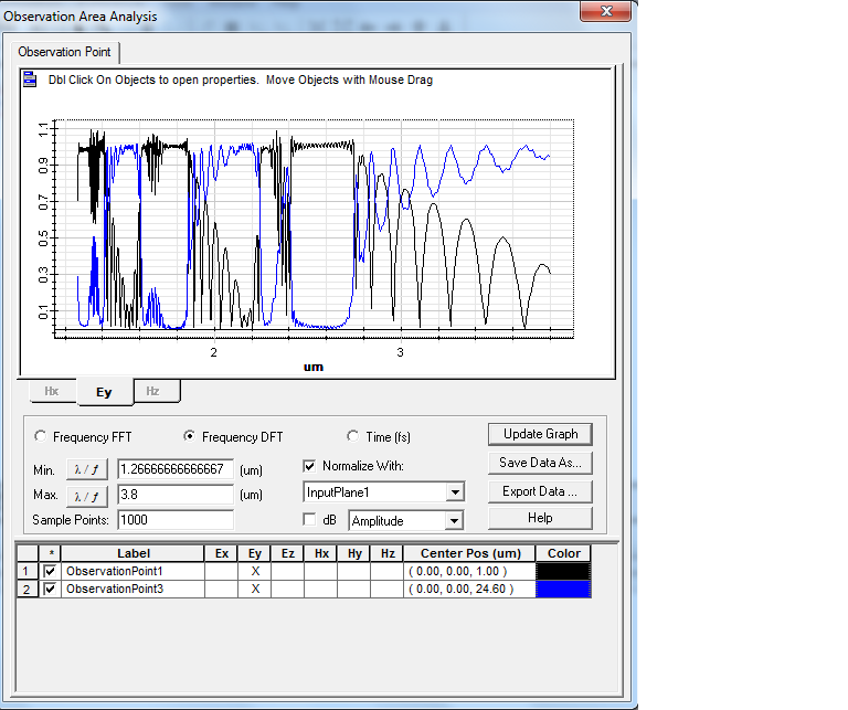
3) When you’re watching your reflected or transmited spectrum normalized in an Observation line, it wants to say that for each wavelength of the simulation, Optiwave mesures the amplitude of its signal. Then divides the reflected or transmited amplitude for the one that the input wave have in this exact wavelength. And, if you add both of the normalized signals you will find that (more or less) they sum 1. But, in case you’re in an Observation point, you have to obtain the data from ‘save data button’ and then make the sqare of them to obtain the (more or less again) result given in the observation area. Of course, after the normalization of the input signal (you can erase the crystal structure and then divide one by one the differnt lambdas). I’ve done it and it fits.
I hope I was helpfull.
Regards,
David.
Hello Damian,
I am not trying to reproduce any particular scintifica article but guess there is bicliography talking about it. I am going to search and if I find something interesting, I pass it to you.
Regards.
DCM
Thanks Damian for answering to me so quick. I realized what you told me (in fact I worte a message to you 8 minutes before your response saying this :)) but the thing now is that I don’t understand that, if I run the simulation without any deffect the band diagram is different depending on the supercell I choose. I am not very sure, but if I have a regular and symetric system, simulating with 1×1 supercells or 1×20 should give me the same band diagram. And I don’t know why it is not like this…
Thanks Damian!
Hello,
Finally I could. I only had to change the supercell value. But there is still something strange: if I simulate without the deffect the structure with a supercell of 1×1 the band diagram is different than the one obtained using more supercells (for example 1×10). Why is that? The bandgap is supposed not to change if the cylinders are the same. Should have only a computational cost … isn’t it?
Thanks,
David
Hi again Damian,
I am sorry to ask so much but I still have the same result. I have realized that the project I attached in the first conversation was wrong: I told you that the material ofthe wafer was silicon and it was air. Also I made a mistake telling you that the cylinders were made with air: actually their material was PBG_atom. So I attach again the project (sorry about that). I made the same distribution you told me in your last message but the reflected and the transmitted signals don’t sum a constant factor (‘analyzer_picture.png’). If I change the materials, I check that it also works uncorrectly (reflection is not the initial signal – transmission (‘analyzer_picture_opposite.png’)) but not in the opposite case and that’s weard I think …
Regards,
David.
Uau!
Thanks a lot!
Let’s see if the results are the expected ones! You’ve been very helpful Damian!
Hello Damian,
First of all, thanks a lot for your fast and helpful response. I see a little bit better why my simulation is not working as I would expect. But the fact is that it would be great for me to check the project you attached me and I can not open it because I am working with a 32.bit version. Could you attach it it ne in this version please?
Thanks a lot, again.
DCM
The graphics.
Attachments:
Ok! Thanks a lot for the explanation and for the biblography attached!