In this example, we will show realization of a WDM ring network using wavelength independent subscriber equipment to share bandwidth [1].
The metro-ring network we modeled operates with 2 wavelength carriers as shown in Figure 1. In this configuration, several subscribers share the bandwidth. For illustration purposes, the network contains one Network Node (NN) and one Access Node (AN). By using a packet format, multiple users can share a single wavelength. All wavelengths are sourced at the NN whose output wavelengths are multiplexed on the ring fiber. NN also contains an associated set of WDMs. The resulting architecture can simultaneously support:
- cost-shared virtual rings (the distribution ring network connected to AN, single wavelength goes around this sub-rings)
- distribution stars with a dedicated wavelength per user (every End Station (ES) uses a different wavelength)
- a combination
Figure 1: Ring network with 4 end stations (subscribers) and 2 access nodes
In the example shown in Figure 1, we have one NN and two ANs (AN1, AN2). In this configuration, two end stations (ES1 and ES 2) share the same wavelength. End users, via a packet protocol as shown in Figure 2, share this wavelength. Incoming packet data is directed to user’s receiver via a 3 dB splitter. Each outgoing packet is created by modulating an incoming “optical chalkboard”, which consists of a string of all ones sourced at the NN. In our example, we modulated two optical carriers at ES1 and ES3. Note that the modulation and packet organization can take place at any sub-ring or star (at any ES that wants to communicate with any other ES). In [1] and [2], SOAs are used to amplify and modulate the incoming signal at every ES. To model this, we have used a combination of an ideal amplifier with 14 dB gain and an ideal amplitude modulator. Therefore, we did not consider any penalty from the SOA characteristics. Details of the ES subsystem is shown in Figure 3.
Figure 2: Details of end stations and writing data on a “chalkboard”
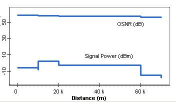
The project is found in the WDM Ring WISE_NRZ_DM.osd file. Here, the bit rate is 2.5 Gbps and laser power at NN is 3 dBm. In this example, ES1 sends data to ES3 by modulating the signal originated from NN on channel 1, over a virtual path marked as “ch1 from ES1 to ES3” in Path manager. In the same way, ES4 communicates with NN on channel 2, over a virtual path marked as “ch2 form ES4 to NN” in Path manager. Figure 4 shows Q factor versus received power at ES3. Figure 5, on the other hand, shows the variation of OSNR and its signal power from ES1 to ES3 as obtained from the Trace tool. Figure 6 shows the eye diagram at ES3 when the received power is about -18 dBm.
Figure 3: Details of ES subsystem
Figure 4: Q factor versus received power at node ES3
Figure 5: OSNR and signal power vs. transmission distance from ES1 to ES3
Figure 6: Eye diagram at ES 3 when received power is about -18 dBm
References:
[1] P. P. Iannone et. al., “A flexible metro WDM ring using wavelength-independent subscriber equipment to share bandwidth”, OFC’00, paper PD38, 2000.
[2] P. P. Iannone et. al., “A transparent WDM network featuring shared virtual rings”, J. Lightwave Tech., vol. 18, pp 1955, 2000.
[3] G. P. Agrawal, Nonlinear Fiber Optics, Second Edition, Academic Press, 1995.


