
The purpose of this lesson is to demonstrate how to design an 8 DPSK pulse generator using the OptiSystem component library. This tutorial includes references to project files that demonstrate some of the steps presented here. Refer to the end of the tutorial for the project file names. You should use the OptiSystem Component Library manual to read the technical description of the individual components presented here.
The first step when creating a project using OptiSystem is to define the global parameters.
Global parameters
To view the global parameters, perform the following procedure.
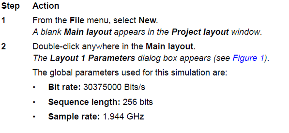
The sample rate can be controlled by changing the number of samples per bit.

Figure 1: DPSK Transmitter global parameters
As you are aware, OptiSystem requires a power of two sequence length, e.g. 64, 128, 256, 512… In this example we will also use an 8 DPSK modulation, which uses 3 bits per symbol. This means that we will have not only a binary sequence that will use the parameter sequence length, but also a M-ary sequence with sequence length divided by 3 (after the DPSK sequence generator). The user should choose the right value for the sequence length that matches the value for the bits per symbol. In order to calculate this value, divide the global sequence length by the bits per symbol, and then take the closest integer number.
For example (8 DPSK):
X = 256 / 3 = 85.33
N = 85
The integer N should be lower than or equal to X, and 256 is a valid value for the sequence length.
Another example if using sequence length of 128:
X = 512 / 3 = 170.67
N = 171
In this case, N is greater than X, and you should use another value for the sequence length. This is critical, because the decoders always convert the M-Ary sequences back to binary, and they will convert the sequence length to the next power of two. This means that if you have 512 bits, N=171, and 3*171 = 513. 513 will be converted to 1024 and the decoder will add zeros to the bit sequence. The received binary sequence will not be correct.
This is not a problem for 256 bits, because N=85, and 3*85=255. 255 will be converted to 256 – the original sequence length. If the bits per symbol are a multiple of 2, in this case X is equal to N.
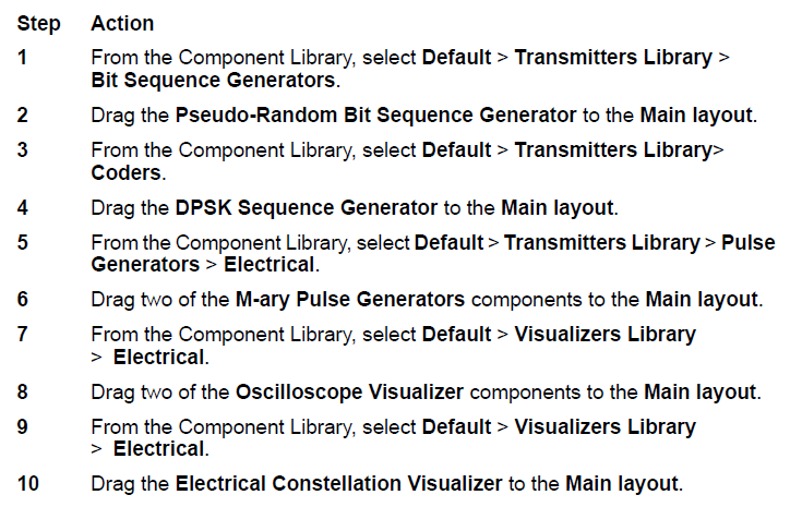
Creating a project
After setting the global parameters, we can start adding the components to design the DPSK transmitter.
From the component library, drag and drop the following components into the layout:
The next step is to set the parameters and connect the components. In this design, for the DPSK Sequence Generator component, we will use the parameters presented in Figure 2. The other component parameters will use their default values.

Figure 2: DPSK Sequence Generator component parameters
The components and visualizers should be connected according to Figure 3.
This layout is equivalent to a DPSK pulse generator. Refer to the OptiSystem project file: “DPSK Step 1 – Pulse Generator.osd”

Figure 3: DPSK pulse generator
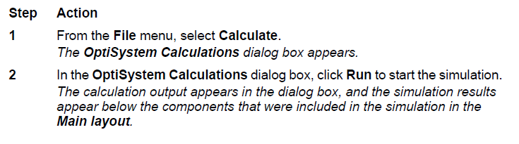
To demonstrate how the global and DPSK parameters affect the simulation results, we can run this simulation and analyze the results of the visualizers.
Running the simulation
To run a simulation, perform the following procedure.
Viewing simulation results
After running the calculation, we can analyze the results from the visualizers.
To display results from a visualizer, perform the following action.
Action
- Double-click on the Electrical Constellation Visualizer to view the graphs and results that the simulation generated.
Note: Double-click again to close the dialog box.
You should see the constellation diagram showing the In-phase and Quadrature-phase on the X- and Y-axis respectively. Figure 4 presents the results of the simulation. This is a well know result for DPSK modulation, using 3 bits per symbol, without phase shift – 8 DPSK. Since we are simulating only 64 bits, not all combinations for 8 DPSK are shown.
")
Figure 4: Constellation diagram for a 8 DPSK modulation (3 bits per symbol)
Action
- Double-click on the Oscilloscope Visualizer to view the graphs and results that the simulation generated.
Note: Double-click again to close the dialog box.
Note the amplitude of the signal. This is a signal with multiple levels; also known as M-ary signal.
For the DPSK there are 5 possible values:
![]()
for both I and Q signals (see Figure 5).

Figure 5: In-phase and Quadrature phase M-ary signals
Using the DPSK Sequence Decoder
We already have the I and Q M-ary signals, however before modulating these signals using a quadrature modulator, we can test to see if the signals can be properly decoded into the original binary sequence. This can be done using a different layout, or reorganizing the previous one.
In order to compare the binary signals before and after coding/decoding, we should modulate the original binary sequence and the decoded sequence using electrical pulse generators, such as the RZ Pulse Generator.
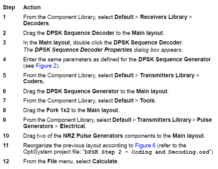

Figure 6: Testing the DPSK sequence coding and decoding
We should see that the electrical signals are the same in both oscilloscopes, since we coded, then decoded the same binary signal. This is demonstrated in Figure 7.

Figure 7: Electrical signals before and after DPSK coding/decoding
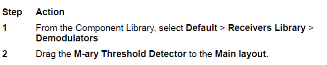
Using the M-ary Threshold Detector
The next step is to detect the I and Q electrical signals using a M-ary Threshold Detector. By using the threshold detector, we can recover the original DPSK sequence, and then decode the sequence into the original binary signal. You can use the system from Figure 3 and the components from Figure 6. However, you will need one additional component:
The main challenge is to set the proper values of the threshold and output amplitudes in the M-ary Threshold Detector component.
Since we know that this is an 8 DPSK, the output amplitudes should be
![]()
The detector will require the threshold values to evaluate the input signal to determine
the equivalent output level, assuming that the input values are the same as the output
values (Figure 8), we will set the threshold values according to the signal input:
![]()
or the equivalent numerical values: – 0.85, -0.353, 0.353 and 0.85.
These values are used to compare the input signal with the threshold according to:
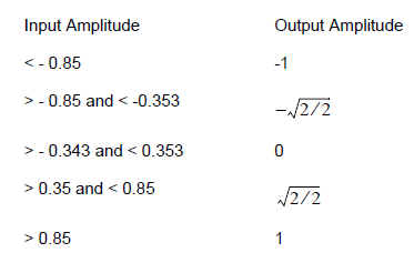
Table 2: Input and output based on threshold amplitudes
Also, the parameter Reference bit rate should be the same bit rate as the input M-ary signal, and this is the original bit rate of the binary sequence divided by the number of bits per symbol: the global bit rate / 3. Figure 8 presents the parameters for both detectors.

Figure 8: M-ary Threshold Detector parameters
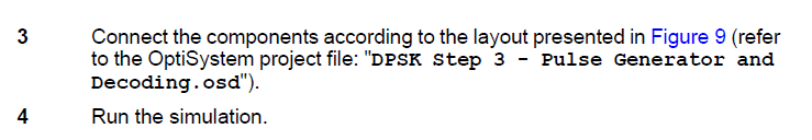

Figure 9: DPSK pulse generator and detector
After running the simulation, you will see that the results for the oscilloscopes at the binary source and at the decoder output are the same (Figure 7). If you don’t have the proper values for the global sequence length, for example, 512 bits, the graphs will be different.
Adding Quadrature Modulation
We already know how to code and decode a DPSK signal; now we can modulate the M-ary signal using quadrature modulation.
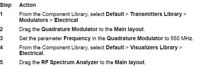


Figure 10: DPSK Transmitter
This was the last step to build our DPSK transmitter, now run the simulation and visualize the spectrum of the signal output (Figure 11).

Figure 11: DPSK Transmitter output
Observe that the center frequency of the signal is the modulation frequency 550 MHz, and that the simulation bandwidth is defined by half or the value of the global parameter sample rate (1.944 GHz / 2 = 972 MHz). This means that if you want to increase the simulation bandwidth to accommodate a higher modulation frequency (>900 MHz), you should change the number of samples per bit in the global parameters window.
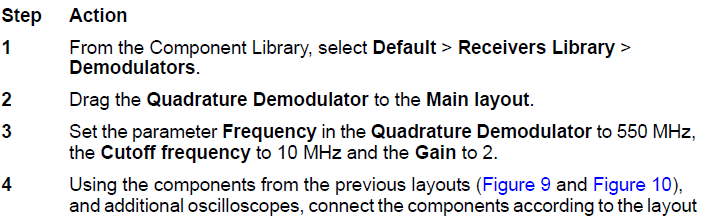
Adding Quadrature Demodulation
We already know how to code, decode and modulate a DPSK signal; now we can demodulate the DPSK signal using quadrature demodulation.
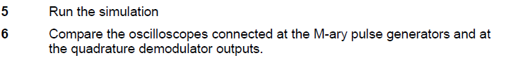
![]()

Figure 12: DPSK transmitter and receiver
For the quadrature demodulator, the Frequency parameter should be the same value as the carrier transmitter frequency. The cutoff frequency again should be adjusted accordingly in order to shape and scale the output signal properly.
The output signals at the quadrature demodulator are presented in Figure 13, the signals are virtually the same as presented in Figure 5, however they are distorted by the quadrature demodulator low-pass filter. If you add a channel between the transmitter and receiver, the signal may have additional distortion and noise.

Figure 13: In-phase and Quadrature phase M-ary demodulated signals
The next step is to compare the binary signals at the transmitter and at the receiver. If the system parameters are correct, you should have the same results as presented in Figure 7.
The layout presented in Figure 12 is a complete project for an 8 DPSK transmitter and receiver. You can use this project as a starting point for other types of modulation, such as QAM and OQPSK. Refer to the OptiSystem Component Library documents for the description of different types of modulation available in the software.
Saving Design Time Using the Modulators Library
The previous transmitter design required multiple components to code the signal, generate the M-ary pulses, and to finally modulate the signal. You can use components from the pulse generator library that include the coders and pulse generators, or components from the modulators library that include the pulse generators and the quadrature modulators.
In the previous layout (Figure 12), delete the DPSK Sequence Generator, the M-ary Pulse Generators, and the Quadrature Modulator and the visualizers connected to them.
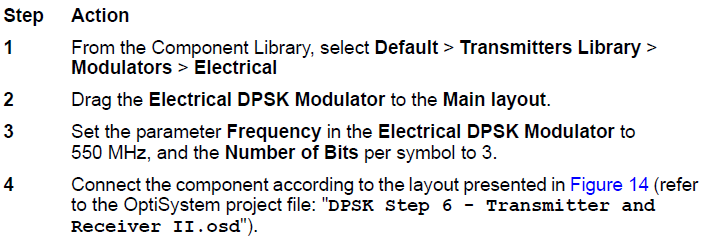
 and receiver")
Figure 14: DPSK transmitter (using DPSK modulator) and receiver
As you can see, by using the DPSK modulator instead the multiple components, the system is faster in making the design than the one in Figure 12. On the other hand, you cannot access all the internal signals that helps you to test and understand the challenges when designing digital modulation transmitters.
Plotting eye diagrams for M-ary signals
OptiSystem can plot and estimate the BER of an optical system for two level (binary) signals. When using M-ary signals, you cannot estimate the values of BER directly, however you can still plot the eye diagrams.

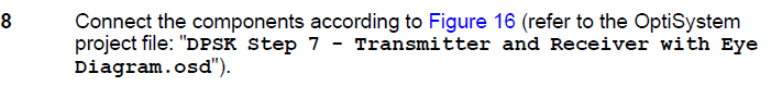

Figure 15: PRBS generator for parameters used to generate M-ary eye diagrams

Figure 16: DPSK system, including components to generate eye diagrams
In this example, we added the Eye diagram tool to plot the M-ary signal at the quadrature modulator output, for the In-phase signal.

The main parameter is the bit rate at the PRBS. It should be the binary bit rate divided by the number of bits per symbol, e.g. M-ary bit rate. This is the same value used in the Threshold detector.

Figure 17: DPSK Eye diagram at the receiver for an 8 DPSK system