
Fiber propagation loss definition
The total fiber loss can be divided into material losses and fiber induced losses.
Material losses include Rayleigh scattering, ultraviolet (UV), infrared (IR) absorption,
and hydroxyl (OH) absorption losses. Material losses are the limiting losses in fibers.
Fiber loss is defined as the ratio of the optical output power Pout from a fiber of length
L to the optical input power Pin. The symbol á is commonly used to express loss in
decibels per kilometer:

Rayleigh scattering model
Because of the granular appearance of atoms or molecules of the glass fiber, light
transmitted through the fiber suffers scattering loss. This is known as Rayleigh
scattering loss.
Rayleigh scattering losses in a fiber are typically determined through experimental
measurement. The loss is expressed in decibels per kilometer through [Buck,
1995[4]]:

For a single-component glass such as Si02

where n0 is the refractive index, p is the photoelastic coefficient, β is the thermal
compressibility, k is the Boltzmann coefficient, and T is the absolute temperature of
the sample.
Ultraviolet absorption model
Ultraviolet or UV absorption results from electronic absorption bands in the ultraviolet
region. The electronic absorption bands are associated with the band gaps of
amorphous glass materials. Absorption occurs when a photon interacts with an
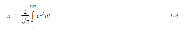
electron in the valence band and excites it to a higher energy level. The UV absorption at any wavelength can be expressed as a function of the mole fraction x of Ge02
[Buck, 1995[4]]:

UV loss is small compared to scattering loss in the near infrared region.
OH-radical absorption model
The OH radical of H2O molecule vibrates at a fundamental frequency corresponding
to IR light wavelength of λ = 2.8μm. Since the OH radical is slightly anharmonic,
“overtones” can occur. These cause OH absorption lines to occur at λ = 1.39,
0.95,and 0.725μm, the second, third, and fourth harmonics of fundamental
frequencies, respectively. Broad peaks can appear [see, for example, Marcuse,
1981[7]]. OH absorption can be characterized by fitting the absorption lines by
Lorentzian or Gaussian method.
Lorentzian fit method:

Gaussian fit method:

In the above two equations, Ai is amplitude, Ai is absorption peak position, and σi
is the width of the i-th absorption line. Using up to seven absorption lines fits the OH
absorption spectrum here.
In contemporary state-of-the-art fibers the hydroxyl-group absorption is greatly
reduced, and only the peak at λ = 1.38 – 1.39μm still retains some practical
importance.
Infrared absorption model
Infrared or IR absorption is associated with the characteristic vibration frequency of
the particular chemical bond between the atoms of which the fiber is composed. An
interaction between the vibrating bond and the electromagnetic field of the optical
signal results in a transfer of energy from the field to bond, thereby causing
absorption.
The IR absorption expression for Ge02 – Si02 glass is [Buck, 1995[4]]:

Macrobending loss model
The macrobending loss Y is a radiative loss when the fiber bend radius is large
compared to the fiber diameter. It is defined as usual by P(z)=P(0) exp (-yz)where
P(0) is the input power and P(z) is the output power at distance z respectively.
Currently OptiFiber implements two different macrobending loss models:
1. The first model uses the closed-form integral formula, published by J. Sakai and T. Kimura [J. Sakai and T. Kimura, 1978[26]]. It is appropriate for calculating the macrobending loss of any LP mode, both fundamental and higher-order, in arbitrary-index profile optical fibers. Using this formula the macrobending power loss coefficient is expressed as a function of the bending radius Rb in the form:
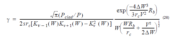
The parameters appearing above are given by:

(the normalized dimensionless frequency)
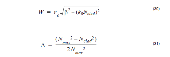
where rc denotes the fibre core radius, Nmax is the maximum value of the
refractive index and Nclad is the cladding index, β is the propagation
constant of the mode, k0 is the prop. constant in vacuum, V is the azimuthal
mode number, s = 2 if v = 0 or s = 1 for v ≠ 0 and Kv is the modified
Bessel function of the second kind of order v.
2. Using the second macrobending loss model the coeficient y can be expressed
as [Snyder and Love, 1983[20]]:
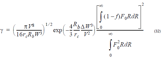
where F0 is the radial field of the fundamental mode:

and N(R) is the refractive index profile of the fiber. The other parameters are
given above.
The two models give similar results for step-index fibers.
The loss coefficient y can be converted to loss in decibels per kilometer units as
follows:
Microbending loss model
Microbending loss is a radiative loss in fiber resulting from mode coupling caused by
random microbends, which are repetitive small-scale fluctuations in the radius of the curvature of the fiber axis.
An approximate expression for the attenuation coefficient is given by [Petermann,
1976[12]]:
where A is a constant, dn is the near field diameter, n1 is the core refractive index
of fiber, k is the free space wavenumber, and p is the exponent in the power law.
Splice loss model
A splice is the dielectric interface between two optical fibers. Any index-of-refraction
mismatch at any point in this interface will produce reflection and refraction of the light
incident at that point. For splicing calculations, we assume that the mode field of
single-mode fibers is nearly Gaussian. The coupling losses for the splicing connectors
can be calculated by evaluating the coupling between two misaligned Gaussian
beams.
Based on the above model, the coupling loss between two single mode fibers is given
by [Miller and Kaminow, 1988[10]]:
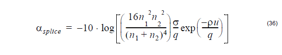
where
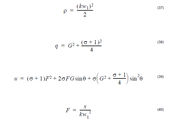
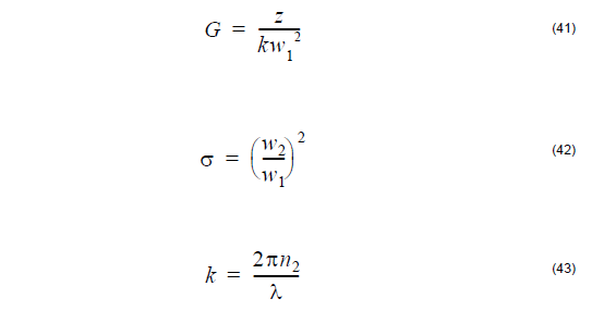
The symbols above are:
n1 – core refractive index of the fiber
n2 – refractive index of the medium between the two fibers
λ – wavelength
W1 – near field mode field radius of transmitting fiber
W2 – near field mode field radius of receiving fiber
x – lateral offset
z – longitudinal offset
θ – angular misalignment