Fiber birefringence definition
The birefringence is defined by the difference between the propagation constants of
the polarization Eigenmodes, that is:
The Differential Group Delay (DGD) per unit length is defined by:

Intrinsic perturbations birefringence
Intrinsic perturbations are accidentally introduced in the manufacturing process and
are permanent feature of the fiber. These include a noncircular core and
nonsymmetrical stress fields in the glass around the core region. A noncircular core
gives rise to geometric birefringence, whereas a nonsymmetrical stress field creates
stress birefringence. These results were obtained by the perturbation theory and
applied only for step index fibers.
Elliptical core birefringence definition
The geometrical anisotropy of a non-circular core introduces a linear birefringence in
the fiber. This birefringence depends strongly on the frequency, or on the normalized
frequency V, at which the fiber is being operated.
The non-circulatory or ellipticity of the core is defined by the parameter ε:
where a and b are respectively the minor and major axis of the elliptical core.
The birefringence induced by an elliptical core is linear. The fast axis and slow axis of
the birefringence corresponds respectively to the major and minor axis of the ellipse.
In the case of a step index fiber, the birefringence
![]()
is given by [Sakai and Kimura, 1981[17]]:
![]()
where

is the relative index difference between the core refractive index n1 and the cladding
refractive index n2.
The wave propagation constant is

The function G(V) in the birefringence formula is given by
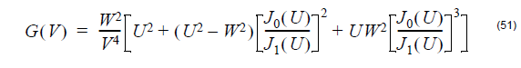
with the following definitions of waveguide parameters
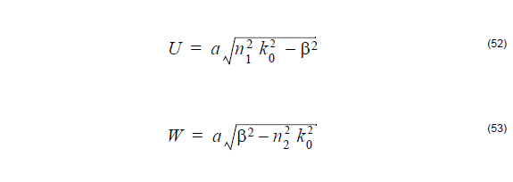
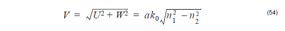
where a is the core radius.
The Differential Group Delay (DGD) per unit length is

where c is the speed of light in vacuum.
Internal stress birefringence definition
Stress birefringence caused by a nonsymmetrical stress field in the core region of a
fiber typically arises in combination with noncircular fiber geometry. The necessarily
different chemical composition of the core relative to the cladding in single-mode fiber
usually results in a slightly different thermal expansion coefficient for the two regions.
This gives rise to radially directed stresses when the fiber is cooled after being drawn.
In an ideal, circularly symmetrical fiber, these stress fields are symmetrical and thus
do not cause anisotropy. However, if there is a noncircular shape to either the core or
the cladding in the preform, the drawn fiber will have internal stress fields that are not
circularly symmetrical.
In a step index fiber with an elliptical core, the birefringence is given by [Sakai and
Kimura, 1982[18]]:
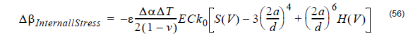
where
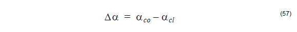
is the difference between the thermal expansion coefficients of the core αco and
cladding αcl
and

is the difference between the room temperature Tr and the softening temperature Ts
of the more heavily doped material.
The remaining symbols in the above internal-stress induced birefringence are:
ε – core ellipticity
v – Poisson’s ratio
E – the Young modulus
C – photoelastic constant
k0 – wave propagation constant in vacuum
a – the average core radius
d – the cladding outer diameter of the fiber
and
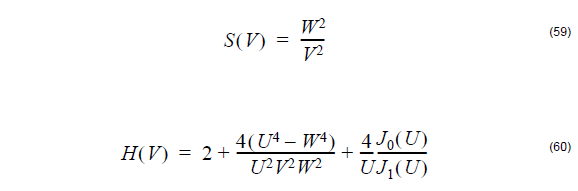
The symbols U,V, and W are defined in section: Elliptical core birefringence definition.
The Differential Group Delay (DGD) per length unit is given by:

Extrinsic perturbations birefringence
Birefringence can also be created in a fiber when it is subjected to external forces in
handling or cabling. Such extrinsic sources of birefringence include lateral stress,
fiber bending and fiber twisting. All three of these mechanisms are usually present to
some extent in spooled and field-installed telecommunications fiber.
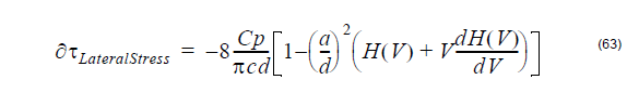
Lateral stress birefringence definition
When two equal and opposite forces p act across an axis of a fiber with a diameter d,
the birefringence induced is linear. The fast axis of birefringence is aligned with the
axis defined by the two opposite forces.
The birefringence is given by [Sakai and Kimura, 1981[17]]:
where
C – photoelastic constant
p – lateral force
k0 – wave propagation constant in vacuum
d – the outer diameter of the fiber
a – the average core radius
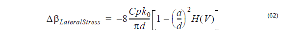
and H(V) was defined previously in the section: Internal stress birefringence
definition.
The Differential Group Delay (DGD) per unit length ∂τLateralStress is:
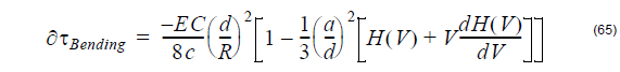
Bending birefringence definition
Bending on a fiber with a bending radius R >> a (fiber core) gives rise to a linear
birefringence. The fast axis of birefringence is perpendicular to the bending plane.
The slow axis is aligned with the bending radius.
The birefringence is given by [Sakai and Kimura, 1981[17]]:
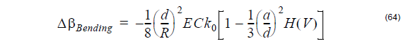
with R being the bending radius, and other symbols are:
d – the outer diameter of the fiber
E – the Young modulus
C – photoelastic constant
k0 – wave propagation constant in vacuum
a – the average core radius
and H(V) was defined previously in the section: Internal stress birefringence
definition.
The Differential Group Delay (DGD) per unit length is:
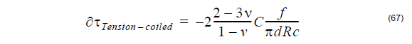
Bending under tension birefringence definition
If we consider a pure axial stress applied to the fiber, simple symmetry considerations
show that there is no induced birefringence. But winding a fiber with axial tension f
onto a drum introduces an additional linear birefringence that adds to the bending
birefringence. This tension-coiled birefringence results from the lateral force exerted
by the drum on the fiber in reaction to the tensile force f.
The definition is given by [Sakai and Kimura, 1981[17]]:

where
C – photoelastic constant
f – axial tension
k0 – wave propagation constant in vacuum
R – bending radius
The Differential Group Delay (DGD) per unit length is given by: