
Home › Forums › SYSTEM › MATLAB Optisystem Co-simulation › Reply To: MATLAB Optisystem Co-simulation
Hi Mohamed,
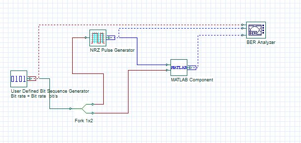
The attached image gives an outline of how the system should be setup. You should start with inputting the electrical signal from OptiSystem into a Matlab component. When OptiSystem runs, it will call the M-file in the Matlab component, process the data, and then export the resulting electrical signal back into OptiSystem.The output signal is then connected to the BER Analyzer.
Also stick with the random data generator from OptiSystem (instead of the generator in Simulink) and input it into the Matlab component. This data array could then be handed over to Simulink (via the Matlab m-file). It will make calculating the BER easier.
I have also enclosed examples of co-simulations between Matlab and OptiSystem. If you are interested, there is also a relevant post in the Knowledge section:
Use of the Matlab Component [Optical System]
The attached files explain the Matlab component in great detail!
Categories
- All
-
Knowledge
Contains a detailed Q&A knowledge base. -
General
All non-technical questions. -
System
Optical system design and analysis. -
Instrument
Communicate and control different kinds of instruments. -
SPICE
Opto-electronic circuit design. -
FDTD
Finite-Difference Time-Domain simulation. -
BPM
Beam Propagation Method analysis and design. -
Grating
Fiber optic grating simulation. -
Fiber
Optical fiber design and characterization. -
Exchange
Users can exchange design files.
(Matlab, C++, etc.)