
Overview
Hollow core fibers guide light by using a photonic bandgap structure in place of a traditional low index cladding material. Since the majority of the optical power propagates through the core air hole region, these fibers are particularly resistant to nonlinear optical effects. Hollow core fibers can offer other advantages like extremely low loss bends, extreme dispersion values and the ability to modify the core material properties by swapping air for some other gas.
Applications
- – High power optics
- – Lasers
- – Pulse compression
- – Dispersion compensation
- – Sensing
- – Bent waveguides
Benefits
- – The VFEM is extraordinarily fast
- – Accurately approximates geometry, which is of utmost importance in hollow core fibers
- – Can search for modes with modal index < 1, a peculiar characteristic of hollow core fibers
- – Uniaxial perfectly matched layers (UPML) can be used to find leaky modes
- – Triangular mesh size can be adapted to accurately approximate electromagnetic field and waveguide geometry
- – Exploiting the symmetry of the waveguide, the simulation domain can be reduced and modes with certain symmetries can be targeted
Simulation Description
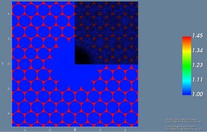
The vector finite element method (VFEM) mode solver can be used to find the guided modes of hollow core fibers. Hollow core fibers have some peculiar properties that make them very interesting but also very difficult to accurately model. The guiding mechanism is provided by the periodic structure that is engineered to have a bandgap in the wavelength range of interest. The modal properties are then highly dependent on the wavelength and the photonic crystal (PC) that surrounds the center defect. This means that the PC geometry must be precisely approximated using a triangular mesh.
A hollow core fiber [1] is shown on the reverse side, where the blue and red refractive indices represent air and silica respectively. Superimposed on the refractive index plot is a generated mesh using two key advantages of the VFEM mode solver. First the simulation domain is reduced by a factor of 4, from the symmetry of the problem. The minimum x and y boundary conditions (BCs) were set to combinations of electric wall (EW) and magnetic wall (MW). The particular combination of EW and MW determine the type of symmetry optical modes take. Second an assumption is made that the electric field distribution of the fundamental mode will be Gaussian in nature. Thus, the mesh is adapted to have a finer resolution near the core of the waveguide.
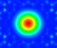
Figure 1: HE11 mode (Poynting vector)
The different modes were found for a wavelength of 620 nm, lattice pitch of 1 micron, and classified according to [1]. A modal index estimate less than 1 was used to find the guiding modes. The HE11 mode was found with a modal index of 0.993. Another cluster of higher order modes was found near a modal index of 0.98. They were classified as the TE01, TM01 and HE21 modes. Plots of the Poynting vector along the direction of propagation are shown in Figures 1-4.
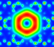
Figure 2: TE01 mode (Poynting vector)
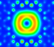
Figure 3: HE21 Mode (Poynting vector)
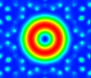
Figure 4: TM01 Mode (Poynting vector)
The adaptive mesh, exploitation of the simulation domain and ability to search for modes near an estimate modal index make the VFEM mode solver an excellent choice for hollow core fiber applications.
References
[1] K. Z. Aghaie, V. Dangui, M. J. F. Digonnet, S. Fan, and G. S. Kino, “Classification of the Core modes of hollow-core photonic-bandgap fibers,” IEEE J. Quantum Electron., vol. 45, no. 9, pp. 1192–1200, 2009.