This lesson demonstrates the application of the uniform fiber Bragg grating component in OptiSystem as a filter.
This lesson has two project layouts. In the first one, a white light source is used. In the second one, a Gaussian pulse is used. The first project layout is shown in Figure 1
Figure 1: Project Layout for filter with uniform fiber Bragg grating component in OptiSystem
The initial spectrum has the form shown in Figure 2.
Figure 2: Initial spectrum of white light source
This layout include sweeps on the Reflectivity in the Main tab of the fiber Bragg grating component.
Figure 3: Main tab of the uniform fiber Bragg grating
Because the reflectivity is connected with the product of coupling length and the length of the gratings (according to the existing exact solution [1]), this sweep corresponds to the change in the coupling length and/or the length of the grating. The comparison of the corresponding reflection spectrum is shown in Figure 4.
Figure 4: Reflected spectrums from uniform Bragg grating for 0.19, 0.59 and 0.99 reflectivity
Obtained results are in a good agreement with what could be inferred from the exact solution for the amplitude reflection coefficient of uniform grating [1]. The corresponding transmission spectrums are shown in Figure 5.
Figure 5: Transmitted spectrums from uniform Bragg grating for 0.19, 0.59 and 0.99 reflectivity
In the second layout, a filter action is demonstrated on the spectrum of Gaussian pulse.
Figure 6: Project Layout for filter with uniform fiber Bragg grating component in OptiSystem using the Gaussian pulse
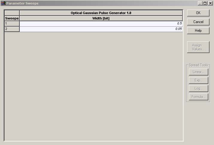
A sweep with the pulse width (0.5 and 0.05 duty cycle in the main tab of Gaussian generator) and respectively with the spectrum of the Gaussian pulses is performed.
Figure 7: Sweep of the duty cycle
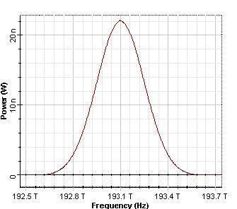
The spectrum of initial Gaussian pulses are presented in Figure 8
Figure 8: Initial spectrums of the Gaussian pulses, duty ratio 0.5 and 0.05 (12.5 ps and 1.25 ps, respectively)
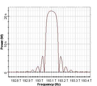
The obtained reflection spectrums are presented in Figure 9.
Figure 9: Reflected spectrums of the Gaussian pulses, duty ratio 0.5 and 0.05, respectively
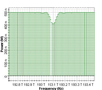
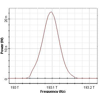
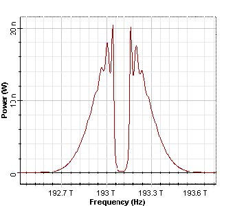
The corresponding transmission spectrums are shown in Figure 10.
Figure 10: Transmitted spectrums of the Gaussian pulses, duty ratio 0.5 and 0.05, respectively
As we can see, because in the second case the bandwidth of the grating (125 GHz) is much smaller than the pulse spectrum, a part of the spectrum of the pulse is reflected.
In conclusion, we have demonstrated the uniform fiber Bragg grating component in OptiSystem as a filter.
References:
[1] S.Chuang, Physics of Optoelectronics Devices, Wiley Series in Pure and Applied Optics, 1995.


