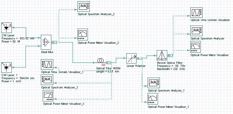
The purpose of this lesson is to demonstrate that the Kerr effect in optical fibers can be used to produce ultra-fast all-optical switch (shutter).
Figure 1: Layout and global parameters
Figure 1 shows the layout and the global parameters.
Figure 2 gives the field configurations. Powerful pump beam, polarized along one of the fiber axis co-propagates with a weak “probe” beam at different frequency linearly polarized at an angle of 45 degrees with respect to a fiber axis. In the absence of the pump, a crossed polarizer blocks the probe beam.
Figure 2: Field configurations
Considering CW conditions, and in the presence of the pump beam, the equations for the EX and EY components of the probe beam are [1].

Neglecting the probe power with respect to that of the pump, the solutions of (1) are:

As shown in Equation 2, the two components of the probe beam acquire different phase shift during their propagation, and consequently, the polarization state of the probe beam changes (from linear to elliptic) and the probe is partially transmitted through the polarizer.
The transmitted power is given by:

Using Equation 2, Equation 3 can be transformed to:

where L is the fiber length. Since the probe and the pump are at different frequencies the pump power transmitted through the polarizer can be easily filtered out.
Figure 3: Probe transmission coefficient as function of pump power
Figure 3 shows the probe transmission coefficient as a function of the pump power as
obtained from Equation 4 and from the simulation for y = 1.284W-1km-1 and L = 50m.
The power dependent transmission coefficient of the device (Equation 4) can be exploited for ultra-fast optical switching and gating, since the fiber nonlinearity is of electronic origin and its response time is very low.
Figure 4 shows a device that performs signal sampling at specified times by a Kerr shutter. Note that here we neglect the fiber birefringence and the fact that the group velocities are different for the pump and probe frequencies.
Figure 4: Signal sampling at specified times by a Kerr shutter
The probe (or “signal”) at 188THz is shown in Figure 5.
Figure 5: Probe at 188THz
Figure 6: Pump at 193 Thz
The pump (at 193 THz) consists of a sequence of short pulses (Figure 6).
Figure 6(a) shows the spectrum of the input signal (pump and probe).
Figure 6(a): Spectrum of input signal
Each pump pulse opens the shutter and the device becomes transparent for the signal at 188 THz. The output appears in the form of “samples” exactly at times corresponding to the location of each pump pulse, as Figure 7 shows. Note that the filters have blocked the pump.
The ultra-fast switching properties of the Kerr-gate can be used for optical imaging in medicine (see [2] and the references therein). Light reflected from the tissue (a strongly scattering medium) is then passed through a Kerr shutter in which (nonlinear) birefringence is induced by short infrared pulses. By recording the light transmitted through the shutter, electronically or by using conventional photography, the shutter enables time-gated images to be acquired with a temporal resolution of a few picoseconds. High-resolution images through scattering (turbid) media may be obtained by selectively sampling the transmitted photons with the shortest flight times (i.e. the least scattered photons).
Figure 7: Results
References:
[1]G. P. Agrawal, “Nonlinear fiber optics”, Academic press, 3rd edition, 2001.
[2]Jeremy C Hebden, Simon R Arridge and David T Delpy Phys. Med. Biol. 42 (1997) 825-840.


