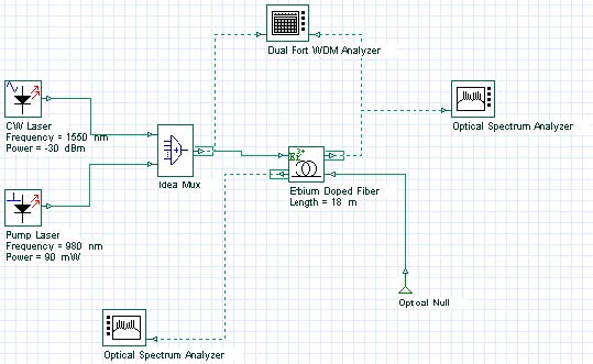
The project file Inline Amplifier.osd shows the characterization of an inline amplifier setup in a single erbium-doped fiber stage, pumped by one 980 nm-pump laser.
A small signal input power is considered in this case, where results with high gain and small noise figure values are desirable. The signal input power is swept from -40 dBm to -20 dBm to enable the checking of the gain, noise figure, output power, and OSNR as a function of signal input power. The signal input power swept is in the layout “Signal input power” contained in the file Inline Amplifier .osd.
After sweeping iterations over the signal input power, the amplifier performance can be checked in the graphs shown in Figure 1.
Figure 1: Graphs presenting the inline amplifier performance setup in a co-propagating pump scheme
Two different pump schemes which consider co- and counter-propagating pump are available, in “Co-pump power” and “Counter-pump power” layouts, shown in Figure 2 and Figure 3. The performance of the inline amplifier with respect to the co- and counter-propagating pump scheme can be checked in the Gain, Noise Figure, and Output Power graphs.
Figure 2: Inline amplifier layout considering a co-propagating pump scheme
Figure 3: Inline amplifier layout considering a counter-propagating pump scheme
The amplifier performance of the amplifier setup in a co- and counter-propagating pump scheme can be compared to the graphs available. Pump wavelength equal to 980 nm was considered in both cases. Gain versus pump power is shown in Figure 4 considering the co- and counter-pump scheme, which allows for the evaluation of the most efficient pump scheme to the EDFAs.
Figure 4: Comparing gain performance of an EDFA setup in a co- and counter-propagating pump scheme
Different parameters can be changed in this example, in which the new results are compared with the previous ones. The wavelength pump power equal to 980 nm, considered in the three different layouts included in this project file, can be substituted with 1480 nm, for example. Different pump power, signal wavelength, and fiber parameters can be considered to perform additional simulations.


