This lesson demonstrates the inhomogeneous broadening in an erbium-doped fiber.
In this lesson, the saturation regime in an EDFA is analyzed based on two approaches:
- homogeneous broadening.
- inhomogeneous broadening.
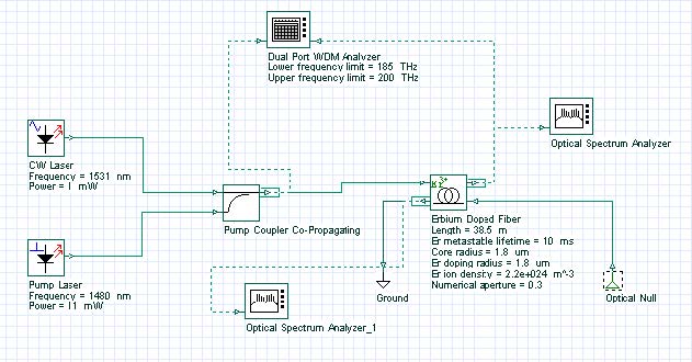
For this purpose, the EDF component is set to the inhomogeneous model and simulations are done for different input signal powers. Figure 1 shows the system used in the simulations.
Figure 1: System layout
The output spectrum is obtained for different input saturating signals. The signal at 1531 nm is the saturating signal and the values of the input signal power are varied from 0 to 1 mW to characterize different levels of saturation. Some of the EDF parameters are displayed in Figure 1, and the Inhomogeneous absorption and emission cross sections loaded by the component are shown in Figure 2.
Figure 2: Inhomogeneous (a) absorption and (b) emission cross section
The equations used in the inhomogeneous model [1] use the homogeneous cross sections. In this case, the component needs to be set to generate the homogeneous cross section from the inhomogeneous cross sections provided by the user, Figure 2.
Figure 3 shows the numerical tab with the parameters set to generate the homogeneous cross sections using 13 Gaussians for the fitting. See the technical description for more information about how to generate the homogeneous cross sections. In this lesson, the value used for the inhomogeneous line width was 11.5 nm.
Figure 3: Numerical tab set to generate the homogeneous cross sections
The homogeneous cross sections generated by the component are shown in Figure 4. These homogeneous cross sections are in good agreement with the homogeneous cross section presented by Desurvire in Figure 4.25 in [1].
Figure 4: Homogeneous (a) absorption and (b) emission cross section
For the homogeneous broadening case, the inhomogeneous line width is considered to be zero or near zero and the system is simulated for the same parameters as in the inhomogeneous case.
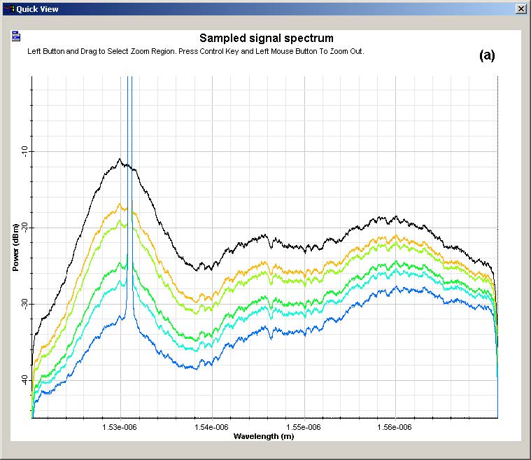
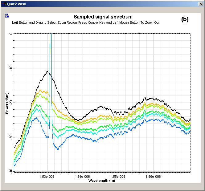
The results found with the simulations are shown in Figure 5 and Figure 6. The output spectrum obtained for the homogeneous and inhomogeneous cases are presented in Figure 5. It is possible to see the behavior of the curves start to become different as the input power is increased. Although in the homogeneous case the saturation seems to act uniformly in the spectrum, in the inhomogeneous case, the effect of saturation is stronger near the saturating signal.
Figure 5: Output spectra in simulations with (a) homogeneous and (b) inhomogeneous model
The compression in the output power is shown in Figure 6. Those curves are obtained by subtracting each saturated spectrum from the spectrum obtained without the saturation signal power. As expected, the compression in the inhomogeneous model is lower than in the homogeneous model for wavelengths far from the saturating signal.
Figure 6: Compression caused by saturation in (a) homogeneous and (b) inhomogeneous cases
These results show the differences between the homogeneous and inhomogeneous broadening in different saturation levels. However, the differences between the homogeneous and inhomogeneous model are more significant than the results presented in [2]. These differences can be related to the use of different parameters for the fiber, such as absorption and emission cross section.
References:
[1]Emmanuel Desurvire. “Erbium-Doped Fiber Amplifier: Principles and Applications”, John Wiley & Sons.
[2]E. Desurvire, J. W. Sulhoff, J. L. Zyskind, and J. R. Simpson. “Study of Spectral Dependence of Gain Saturation and Effect of Inhomogeneous Broadening in Erbium-Doped Aluminosilicate Fiber Amplifiers”. IEEE Photonics Technology Letters, Vol. 2 Feb. 1994, Page(s): 282 -284.


