This lesson shows the influence of signal excited-state absorption (ESA) on the performance of an EDFA.
The effect of signal ESA happens because a signal photon is absorbed by an erbium ion in an excited state, thereby promoting it to an even higher energy state and causing degradation in the amplifier efficiency. This effect is wavelength dependent since it depends on matching photon energies to the transition energies between excited-states of the Er3+ ion.
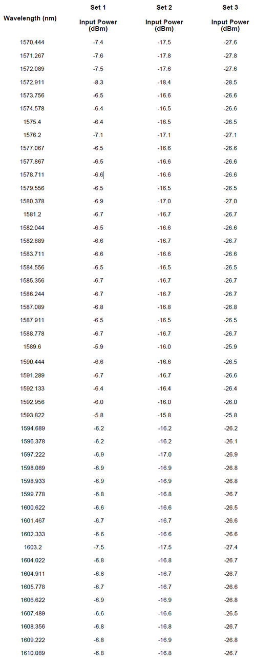
To show the impact of signal ESA on the EDFA performance, the system shown in Figure 1 was used in the simulations. It consists of a set of 47 input signals (see table 1) multiplexed by an ideal multiplexer. The EDFA has a co-propagating pump signal at 1480 nm and some losses in the system are considered using optical attenuators. The gain and NF figure for each channel is calculated using the Dual Port WDM Analyzer component.
Figure 1: System layout used to analyze the performance of the EDFA
Some of the EDFA parameters are displayed in Figure 1. The simulations are taking into account the Rayleigh scattering effect too, but this effect does not cause any considerable difference in the results and it could be neglected in this case.
When the ESA effect is taken in account, the user has to pay attention to the way that the ESA cross section is loaded. The Erbium doped fiber component accepts two formats for the ESA cross section:
(1) The file with the ESA cross section contains the emission cross section and the ESA cross section together,
![]()
(2) The file contains only the ESA cross section.
For the first case, the user has to check the box extract ESA and the component will extract the ESA cross section from this file. Figure 2 shows an example with the enhanced tab for the two cases. As we can see in Figure 2, the signal ESA peak is at 1680 nm.
Figure 2: ESA cross sections
The simulations were done for three sets of signal input powers. Table 1 shows the wavelength and input powers for the 47 channels of each set.

Table 1: Signal wavelengths and input powers of each channel in the three different sets used in the simulations
Two simulations were done for each set, one considering the ESA effect and other neglecting the ESA. In this way, the ESA impact in the results will be clearer. The gain and noise figure results found for each set are shown in Figure 3.
Figure 3: Gain and noise figure results for signal input powers: Set 1, Set 2, and Set 3
In the graphs, it is possible to see that in all sets, the difference in the results obtained with ESA and without ESA starts to become serious for wavelengths larger than 1600 nm. The ESA effect, as expected, caused a considerable decrease in the gain for λ > 1600 nm.
From these results it is possible to conclude that the ESA effect cannot be neglected in the design of an L-band amplifier when the signal band goes beyond 1600 nm.
References:
[1]Emmanuel Desurvire. “Erbium-Doped Fiber Amplifier: Principles and Applications”, John Wiley & Sons.
[2]P. C. Becker, N. A. Olsson, and J. R. Simpson. “Erbium-Doped Fiber Amplifiers: Fundamentals and Technology”. Optics and Photonics, 1999.


