Encircled flux, as the name implies, describes the flux encircled within a circular radius inside the fiber.
Encircled flux is often quantified as the radius from the center of the fiber required to encircle 25% and 75% of the light energy through the fiber.
The power distribution of a fiber described by the encircled flux value is a crucial factor in ensuring the required data transmission rate in Gigabit Ethernet systems.
This tutorial describes the encircled flux simulation using the Encircled Flux Analyzer.
System setup
Using the default global parameters, we can start adding the components to design the basic encircled flux simulation layout.
From the component library drag and drop the following component in to the layout:
- From “Default/Transmitters Library/Optical Transmitters”, drag and drop the “Spatial Optical Transmitter” into the layout.
- From “Default/Passives/Optical/Connectors”, drag and drop the “Spatial Connector” component into the layout. Set the parameters X and Y shift to 10 μm.
- From “Default/Optical Fibers/Multimode”, drag and drop the “Parabolic-Index Multimode Fiber” into the layout.
- From “Default/Visualizers Library/Optical”, drag and drop three instances of the “Spatial Visualizer” into the layout.
- From “Default/Visualizers Library/Optical”, drag and drop three instances of the “Encircled Flux Analyzer” into the layout.
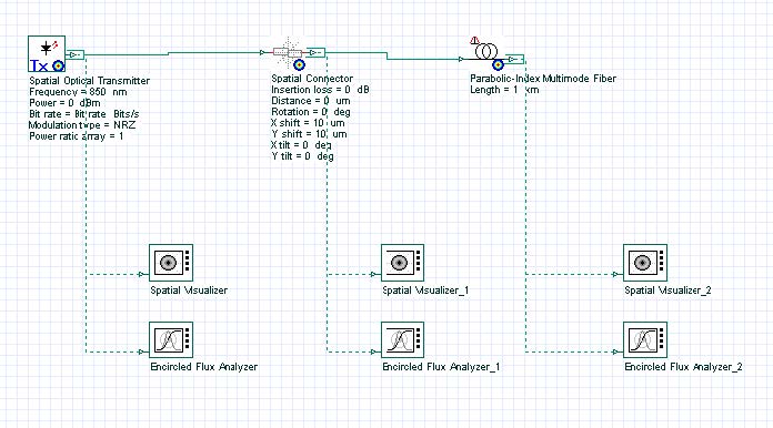
The next step is to connect the components according to the Figure 1.
Figure 1: Multimode link and encircled flux measurement
For this example, the optical transmitter will generate one Laguerre-Gaussian spatial mode LG00, with spot size equal to 10 μm.
The spatial connector has an X and Y-axis shift of 10 μm. The fiber has 25 μm radius and this is the same analysis radius for the encircled flux analyzers.
Running the simulation
We can run this simulation and analyze the results:
- To run the simulation, you can go to the File menu and select Calculate. You can also press Control+F5 or use the calculate button in the toolbar. After you select Calculate, the calculation dialog box should appear.
- In the calculation dialog box, press the Play button. The calculation should perform without errors.
Viewing the results
In order to see the results, double click the Encircled Flux Analyzer.
Using the Encircled Flux Analyzer, you can see the encircled flux and average intensity of the signals.
Figure 2 presents the total signal output (spatial) and the encircled flux graphs for each of the analyzers.
Figure 2: Spatial profile of the total field using the spatial visualizer and the encircled Flux Analyzer displaying the encircled flux graph for each signal
The first graph (left) shows the transverse mode at the transmitter output. The mode is centered at 0,0 and the encircled flux graphs show the maximum flux approximately at 10 μm.
After the spatial connector, the transverse mode (center graph) is shifted by 10 μm and the maximum flux is at approximately 20 μm, as expected after the X and Y-axis shift.
The last graph (right) shows the sum of the transverse modes at the fiber output. The signal is centered at 0,0 and the encircled flux graph shows the maximum flux at 20 μm.
The Encircled Flux Analyzer can be added to any output port and the user can easily recalculate the graphs by changing the analysis radius or number of points and pressing <ENTER>.
The user can also create a parameter sweep of the connector shift and see the changes of the encircled flux graph.
- Remove the multimode fiber and the visualizers connected to the fiber from the layout
- In the spatial connector, set the parameter X and Y shift mode to sweep.
- Set the sweep values to 0,2,4,6,8,10 mm for both parameters.
- Run the simulation
Using the Project browser, we can compare the encircled flux graphs per each sweep (Figure 3).
Figure 3: Encircled flux graphs for each sweep of the X and Y shift


