This lesson demonstrates that the propagation of a CW beam inside an optical fiber is inherently unstable due to the interplay between the anomalous GVD and SPM.
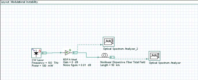
The layout and the parameters are shown in Figure 1.
Figure 1: Layout and parameters
The CW Laser is used as a pump source (Figure 2). Its “Linewidth” is set to zero because we are interested in the interaction between powerful CW radiation and a weak broadband (“white”) noise.
Figure 2: CW Laser parameters
The EDFA is used only as a noise source (Figure 3). Its “Gain” is set to zero dB, which means that the power of the input signal from the laser is left unchanged and some noise is added to it to form the “CW signal + white noise” combination at the input of the optical fiber. The Y-polarization (associated with the noise, since the signal from the laser is X-polarized, but the noise is unpolarized) has been filtered out. This is done for the following reason: at the beginning of each simulation, the optical fiber component checks the polarization state of the input signal.
Figure 3: EDFA parameters
If two polarization components are detected, the vector model is used, regardless of the choice made under the “Main” tab of the fiber component (see Figure 4). The vector model takes twice the time necessary for a scalar simulation. The setup for the optical fiber component is shown in Figure 4.
Figure 4: Optical fiber component parameters
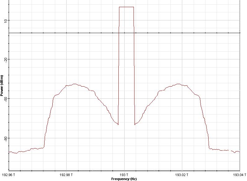
Figure 5 shows the input and output fiber spectra.
Figure 5: Fiber input and output spectra with resolution bandwidth of 0.04nm
It can be seen that the noise components within a certain frequency band around the
pump are amplified [1] i.e. P(Ω, L) = P(Ω, 0) exp(g(Ω)L) .
The gain g is given by [1]:

where

and Ω is the noise frequency shift with respect to the pump frequency.
Gain Equation 1 is maximum at two frequencies (see Figure 5) given by:
In the case detailed in this lesson:

and

so

Essentially, the same value is obtained from Figure 5. The value of the gain at this frequency shift from Equation 1 is:

where L is the fiber length.
Therefore, in dB units, the amplification at this frequency is:

From Figure 5, the output power level at this frequency is ,P(Ωmax ,L) ≈ –38dBm,
while the input noise power is frequency independent and is P(L = 0) ≈ –92dB,
which gives 54dB for the peak amplification.
Figure 6: Fiber output spectrum with dispersion parameter of
β2 = 20ps2 / (km)
Figure 6 gives the output spectrum as obtained when the value of the GVD parameter
was set to β2 = 20ps2 / (km) (normal GVD).
In accordance with Equation 1, no amplification is evident in this case.
Reference:
[1]G. P. Agrawal Nonlinear Fiber Optics, Academic Press (2001).


