To run the simulation, perform the following procedure.
| Step | Action |
| 1 | From the Simulation menu, select Calculate 2D Isotropic Simulation.
The Simulation Parameters dialog box appears. |
| 2 | Under Simulation technique, click Simulate As Is (see Figure 23). |
Figure 23: Simulation Parameters dialog box
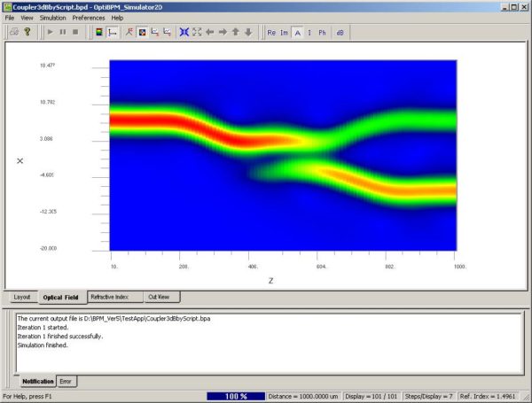
The simulator output appears as shown in Figure 24.
Figure 24: Simulation results
| As Figure 24 shows, this coupler is not an ideal 3dB coupler because more power is transferred to the lower branch than to the upper branch. Moving the waveguides farther apart would reduce the coupling. You can run many simulations with various separations to find the best design. | |
| 3 | Close the simulator and the analyzer. |
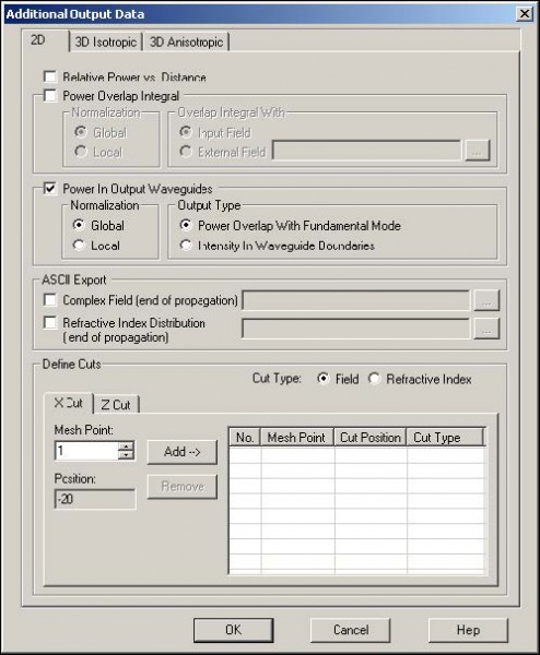
| 4 | In OptiBPM_Designer, from the Simulation menu, select Additional Output Data.
The Additional Output Data dialog box appears (see Figure 25). |
| 5 | Select Power In Output Waveguides.
Note: The output power in the two output waveguides will be passed to the Analyzer. |
Figure 25: Additional Output Data dialog box


