There are several possibilities to describe basic photonic components numerically. We will briefly mention some fundamental properties and mainly their practical limitations of these simulation methods. When necessary, we will refer to the pertinent references.
We can start with the Beam Propagation Method (BPM). The last two decades have been devoted to the extensive study as well as to the extensive exploitation of the BPM in the photonic field. In fact, this method is based on the numerical description of the natural unidirectional propagation of the light beam (see [1] and the references therein). The schematic in Figure 1 depicts the well-known four port coupler, one of the most typical examples being studied by BPM (please note the sizes, especially the slopes of the waveguides). We explain the fundamental limitation of the BPM with this example.
Figure 1: Four-port coupler
The reason of the unidirectional properties of the BPM is obvious, since the method is derived under the paraxial approximation. This yields an accurate analysis just in the close vicinity of the longitudinal axis. The propagation direction is also indicated on the schematics above. Some relaxation (say up to 60 degrees deviation from the longitudinal direction) can be achieved by the wide angle BPM. Anyhow, this can be applied just for very specific photonic arrangements. Further improvement is available using the so called bi-directional BPM (backward propagating to the formerly assumed direction) and some other minor modifications. These improvements have been worthwhile indeed, but they are not still satisfactory for our purpose. Apart from these limitations, the BPM techniques are relatively fast and they can also be used to study quite long devices (up to a few millimeters). The speed is approximately related to the area of the simulation window. We will reconsider this fact below.
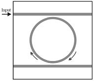
Another numerical method is the finite difference time domain method (FDTD) [3]. The method is complex and it is based on the direct numerical solution of the Maxwell’s equation in time domain. Unlike BPM, the FDTD is omnidirectional. The schematic in Figure 2 shows a suitable example for the FDTD, the ring resonator.
Figure 2: Ring resonator
The light is introduced into the device through the upper waveguide, however it later propagates along the ring circumference, which would be unacceptable in BPM. The method can also simulate scattering phenomena, nonlinear effects and many others. The FDTD has one crucial limitation as well. Namely, the device design is strictly space limited, say to several tenths micrometers in size (in 3D). The reason for this is the huge CPU consumption during the simulation.
The last method is the exploitation of (quasi) analytical techniques like the coupled mode theory (CMT). Our product OptiGrating is actually a computer automated CMT. The CMT is mainly appointed for the description the light interaction with the media containing gratings [4]. A grating is obviously very specific component of a photonic circuit and we will be analyzing any grating appearing in a layout separately through the paper, although some sophisticated numerical methods (even like FDTD) can be used to describe the light response from the interaction with a grating. One can also use the CMT advantageously for some basic classification of various waveguide configurations (or any coupling phenomena).


