To draw the Linear Waveguide, perform the following procedure.
| Step | Action |
| 1 | From the Draw menu, select Linear Waveguide. |
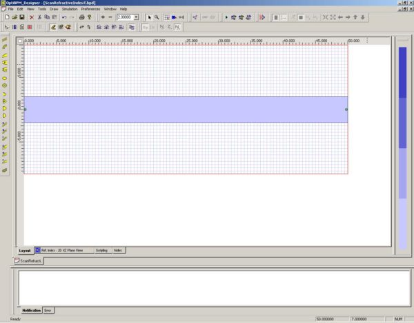
| 2 | Draw the waveguide in the center of the wafer and covering the length of the wafer (see Figure 8). |
Figure 8: Draw Linear Waveguide
Inserting the Input Plane
To insert the Input Plane, perform the following procedure.
| Step | Action |
| 1 | From the Draw menu, select Input Plane. |
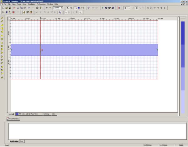
| 2 | Click in the layout and position the Input Plane at 10 microns (see Figure 9). |
Figure 9: Insert Input Plane
| 3 | Double-click the Input Plane.
The Input Plane dialog box appears. |
| 4 | Click the Input Fields 2D tab, and then click Edit.
The Input Field dialog box appears. |
| 5 | Click All to move the waveguide for input from the Waveguides window to the Fields window (see Figure 10). |
Figure 10: Input Field dialog box—move waveguide
| 6 | To save the setting and return to the Input Plane dialog box, click OK. |
| 7 | To return to the main layout, click OK. |


