To create a linear waveguide formed by the Titanium Diffusion in Lithium Niobate, perform the following procedure.
| Step | Action |
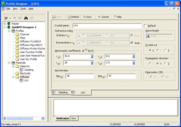
| 1 | Create the following dielectric material (see Figure 1):
Name: Cladding Refractive index (Re:): 1 |
Figure 1: Profile Designer — Cladding
| 2 | Create the following diffusion material (see Figure 2):
Name: LN1 |
Figure 2: Profile Designer — LN1
| The substrate is defined as diffused material. The name ‘diffused’ in the materials denotes substrates suitable for the diffusion process. By default, the diffused materials have the structure and parameters of Lithium Niobate. As a result, you must choose the desired orientation of the sample and propagation direction. You can change the properties (such as refractive indices and electrooptic coefficients) so that other materials can be modeled, provided that Equation 21 applies and polarization coupling can be neglected.
Once the necessary materials are defined, it is possible to define diffused profiles. There are three predefined diffused processes (see “Titanium Diffusion in Lithium Niobate” on page 71 for more information). |
|
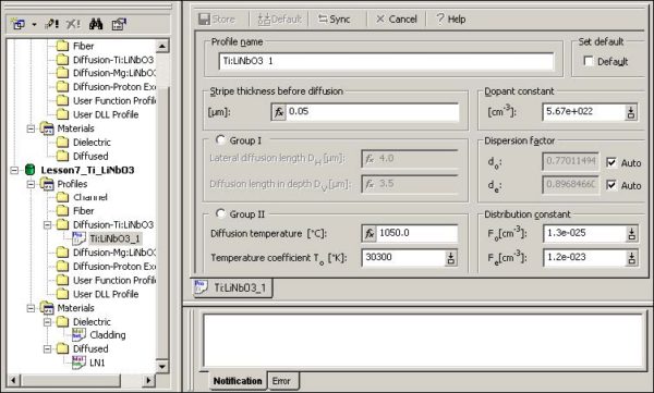
| 3 | Create the following Diffusion–Ti:LiNb03 material (see Figure 3):
Name: Ti:LiNb03_1 |
Figure 3: Profile Designer — Ti:LiNb03
| Note: You can use the default values, change the defaults, or apply functions.
You can change: • ordinary and extraordinary refractive index • electrooptic coefficients • crystal cut • propagation direction • polarization The wavelength input in the profile determines the refractive index boxes in the auto mode, but does not influence simulations. The wavelength of the simulation process is set in “Setting the simulation parameters” on page 321. |
|
| 4 | Close the Profile Designer. |


