To assign paths to the waveguides, perform the following procedure.
| Step | Action |
| 1 | From the Edit menu, select Edit Mode > Monitor Paths.
The Path Monitor dialog box appears (see Figure 3). |
Figure 3: Path Monitor dialog box
| 2 | Click New.
The buttons in the dialog box change (see Figure 4) and the cursor changes into a link. |
Figure 4: Path Monitor dialog box — different buttons
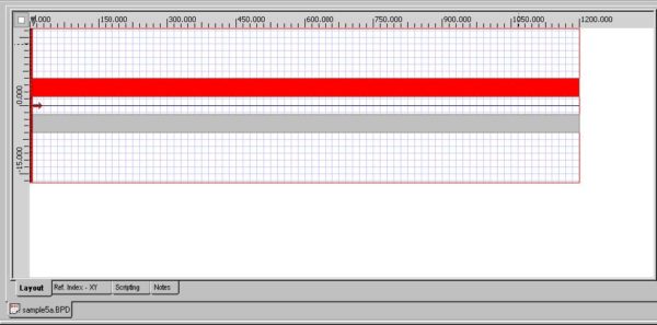
| 3 | In the layout window, click the first waveguide. The defined path turns red (see Figure 5). |
Figure 5: First red waveguide
| 4 | To apply the path, click Finish.
Path 1 appears in the drop-down list (see Figure 6). |
Figure 6: Creating Path1
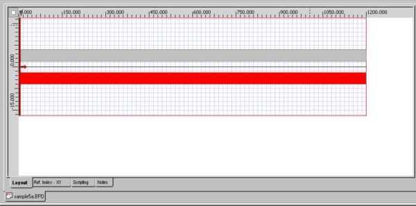
| 5 | Repeat steps 2 to 4 to assign a path to the second waveguide (see Figure 7).
Path 2 appears in the drop-down list. |
Figure 7: Second red waveguide
| 6 | To return to the layout window, click OK.
The waveguides change back to the original color in the layout window. |
| 7 | In the Layout Window, go to Simulation >> Path Monitor Type… and select Power overlap integral with fundamental mode with Global Normalization. |
Figure 8: Path Monitoring Type


