
Our goal here is to demonstrate how to use OptiSystem to simulate transient control schemes to avoid or minimize the impacts of transient effects in the system performance.
As is well known, failures in some channels and/or add-drop of channels due to network reconfiguration can cause power transients that cause error bursts, which are unacceptable to service providers.
To overcome this problem, several schemes to protect amplified networks against power transients have been developed. Here we have worked on one control scheme: EDFA gain clamping, which will be demonstrated in the next section.
In the examples simulated here, we have used a 16-channel WDM system. The addition and dropping of 8 channels are simulated by modulating the optical signal by a square wave at a low bit rate of 4K bits/s.
The transmitter setup configuration and the optical signal waveform at modulator output are shown in Figure 1.
Eight signals are dropped at t = 1.5 ms and added back at t = 5.5 ms. The signal power for each channel is -20 dBm (10 mW) and the modulated and surviving channels have the channel spacing of 1.6 nm between each other.
The sample rate used in the signals was enough to allow the delay due feedback loop to be considered in the simulations.
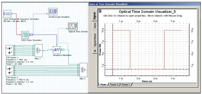
Figure 1: Transmitter setup configuration with 16 channels, where 8 channels are modulated to represent add-drop of channels in the system. One modulated optical signal is shown in the optical visualizer.
Gain clamping
There are two basic configurations of EDFA gain clamping [1].
In the first configuration, the Fabry-Perot laser structure is used with two band-pass reflectors placed in the input and output ends of the amplifiers. The laser wavelength is determined by the center wavelength of the reflectors.
The laser cavity loss is determined by the peak reflectivity of the reflectors and losses between the two reflectors.
One example of this configuration can be seen in Figure 2
Two components appear in this setup. They were created to allow the multiwavelength time-driven simulations, and consequently the transient control simulations.
The “Convert To Samples” component receives the optical channels in this input port and transforms these block signals in individual samples that are launched forward sample by sample in the correspondent time step.
The other component is the “Convert From Samples”, which does the opposite. It receives the individual samples of each channel and assembles the different channels.

Figure 2: Gain-clamping EDFA in a Fabry-Perot laser configuration
We have run the simulation with the drop and add of 8 channels at 1.5 ms and 2.5 ms, respectively. The EDFA was designed to give a gain of approximately 19 dB for each channel. Simulation results for the surviving channel at 1540.3 nm can be seen in the Optical Time Domain Visualizer show in Figure 3 Small oscillations are present exactly at the point where the channels are dropped and added.

Figure 3: Optical surviving channel at 1540.3 nm after the EDFA in a Fabry-Perot laser configuration
In the second configuration, the ring laser structure is used.
Part of the signal and ASE is coupled in one end of the amplifier and fed back to the amplifier input through a feedback loop. In the feedback path, the signals (including ASE) are filtered and attenuated to control the lasing conditions.
Figure 4 shows the gain clamping EDFA setups with the feedback loop including a band-pass filter and an attenuator.

Figure 4: Gain-clamped EDFA in a ring laser configuration
The same add-drop simulation was done for the gain-clamped EDFA ring laser. The EDFA was designed to give a gain of approximately 18 dB.
Figure 5 presents 4 surviving channels after the EDFA amplifier. We can verify the oscillations caused by the drop and add of channels and see that the oscillations are higher and faster when the channels are dropped.

Figure 5: Output signal power of 4 surviving channels
The simulations results presented here are in agreement with previous results presented in the literature. Simulations are not limited to these control schemes. Variations in the previous control schemes can be introduced.
References
[1] A. Yu and M. J. Mahony. “Design and Modeling of Laser-Controlled Erbium-Doped Fiber Amplifiers”. IEEE Journal of Selected Topics in Quantum Electronics, Vol. 3, Issue: 4, Aug. 1997 pp.1013 – 1018.