There are many decisions to make regarding system implementation of specific amplifiers.
To make these decisions, a group of typical key characteristics must be extracted from the amplifier. For example, the gain and noise figure versus the input signal wavelength, input signal power or input pump power.
To extract the key characteristics of the optical amplifier, OptiSystem allows the user to easily iterate over these parameters and characterize the amplifier design.
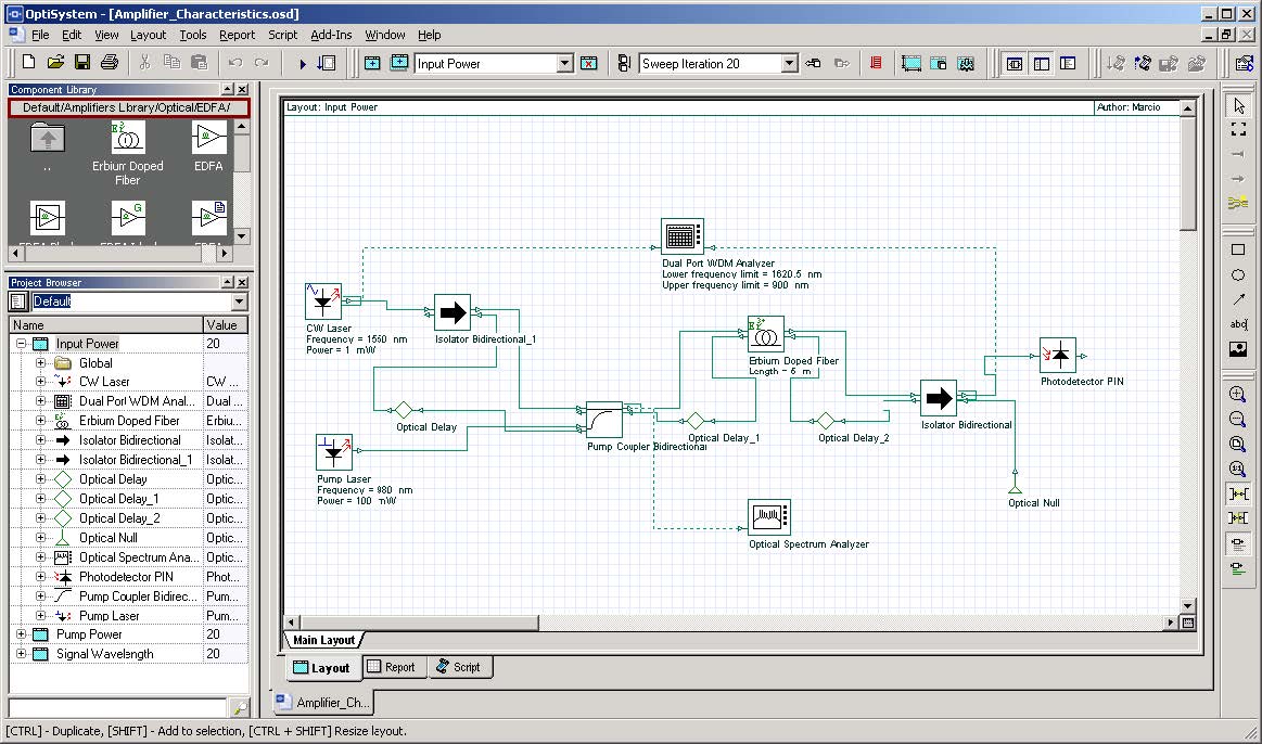
The project “Amplifier Characteristics.osd” shows how to obtain the gain, noise figure and output power versus input power and signal wavelength.
The calculations are based on results from a WDM Analyzer inserted between two isolators. The user can replace the amplifier between these isolators and obtain the same curves for different amplifiers.
Figure 1: Project “Amplifier Characteristics.osd”
Loading the project
- Go to the OptiSystem sample files folder, “…Optiwave SoftwareOptiSystem OptiSystem 9SamplesOptical amplifiers”.
- Open the Project “Amplifier Characteristics.osd”.
This project has three layout versions
- signal wavelength
- input power
- pump power
In the version “Signal Wavelength”, the iterations are swept over the laser signal wavelength and generate the following graphs:
- Gain x Wavelength
- Noise Figure x Wavelength
- Output Power x Wavelength
In the version “Input Power”, the iterations are swept over the laser signal power and generate the following graphs:
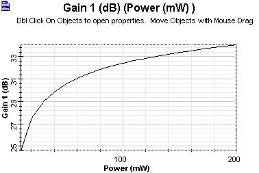
- Gain x Input Power
- Noise Figure x Input Power
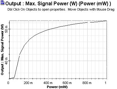
- Output Power x Input Power
In the version “Pump Power”, the iterations are swept over the pump power and generate the following graphs:
- Gain x Pump Power
- Noise Figure x Pump Power
- Output Power x Pump Power
Running the simulation
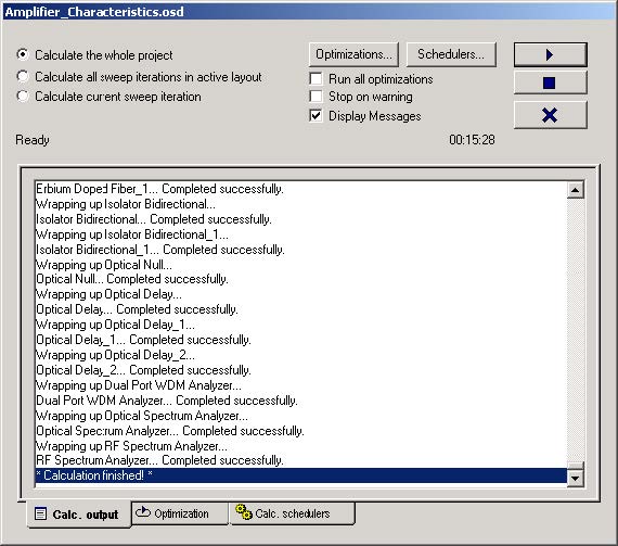
- To run the simulation you can go to the File menu and select Calculate. You can also press Control+F5 or use the calculate button in the toolbar. After you select Calculate, the calculation dialog box should appear.
- In the calculation dialog box, press the Play button (Figure 2).
Figure 2: Calculating project
Viewing the results
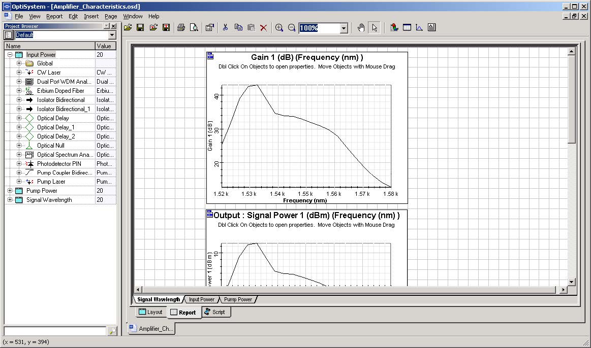
- Go to the report page (Figure 3).
Figure 3: Report page
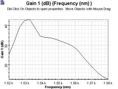
Figure 4, Figure 5, and Figure 6 display some of the graphs that are generated for this simulation.
Observe the Gain x Wavelength, Output Power x Input Power and Gain x Pump Power for the amplifier.
Figure 4: Gain x wavelength
Figure 5: Output power x input power
Figure 6: Gain x pump power


