
Overview
As optical systems move towards an integrated platform, the modelling of high refractive index contrast, sub-wavelength dimension waveguides becomes more important. These properties require a mode solver that can both faithfully approximate the geometry and approximate the electromagnetic field. The waveguide dimensions and electromagnetic field area-of-interest may be multiple orders of magnitude different, as is the case for Long Range Plasmon Polaritons.
Applications
- – Silicon photonics
- – Waveguide design
- – Long Range Plasmon Polaritons
- – Hollow Core Fiber
- – Sub-wavelength optics
- – Bent waveguides
Benefits
- – The VFEM is extraordinarily fast and accurate
- – Full vector formulated anisotropic mode solver
- – Capable of using fifth order interpolatory hybrid vector/nodal elements, which remove spurious solutions and drastically increase accuracy
- – Symmetry of the layout can be exploited to reduce simulation domain size
- – Uniaxial perfectly matched layers (UPML) can be used to find leaky modes
- – Triangular mesh size can be adapted to accurately approximate electromagnetic field and waveguide geometry
- – Modal index estimate increases speed and can be used to search for particular optical modes
- – Employs transformation optics to calculate precisely the modes of a bent waveguide, even for a very small radii of curvature
Simulation Description
Before comparing the vector finite element method (VFEM) to other mode solvers, the accuracy of the different order basis functions was tested. The simplest type of waveguide is a uniformly dielectric loaded microwave waveguide. The core is a simple dielectric and the cladding is considered a perfect electric conductor, representing the rectangular metal walls.
The following graph shows the relative percent error between the VFEM result and the analytical result. The error is plotted as a function of Degrees of Freedom (DoF) resulting from the FEM mesh (the DoF is derived from the number of mesh points).
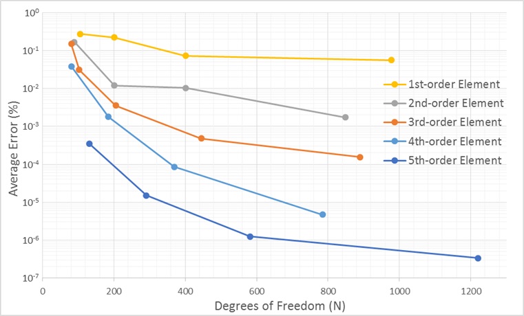
Figure 1: Average error of VFEM calculation
The error for the first five modes is averaged and plotted in Figure 1. It is clear that increasing the order of the basis functions leads to a more accurate result for the propagation constant. At x = 400, increasing the order of the basis functions equates to almost an order in magnitude higher accuracy. It is also important to note that the largest average error is only 0.3%.
Mode solvers using different methods are compared for a high contrast optical fiber, with a core refractive index of 1.5 and a cladding of 1.0. Although this might not be considered as high contrast as SOI waveguides, it is more than enough for our purposes. The cross section of the waveguide is shown on the reverse side.
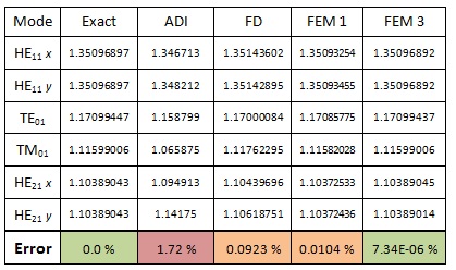
Table 1: Calculated modal index using various mode solvers. The average error in the modal index is included.
The above table shows the calculated modal index for the first six fiber vector modes. A fiber vector solver is used as the benchmark and labelled “Exact”. In addition, ADI, FD and FEM solvers are used to calculate the fiber modes as well. The FEM is split into two groups: The first uses first order elements and the second uses third order elements. Not shown in the table is the amount of time each solver took. The FEM calculation time was matched to roughly the same time the FD solver took, (~109 seconds for the FD, ~65 seconds for the FEM).
This table demonstrates a major advantage of the FEM mode solver and a major drawback of the ADI. The ADI method is fast, but has trouble finding accurate higher order modes and its accuracy gets worse for higher constrast waveguides. The FD method is better than the ADI, however, the most accurate method is the FEM. This is not only true for fiber modes, but extends to rectangular and waveguides of arbritrary shape.
One of the major reasons the FEM solver is so much more accurate is the way it approximates the geometry. The ADI and FD uses small rectangles to sample the index of refraction, which leads to a staircase approximation of a diagonal line or curve. In theory, the rectangular cells can be reduced in size until the staircase is a better approximation, but in practice it still leads to considerable error. The FEM solver uses a triangular mesh which can approximate diagonal lines to a high level of accuracy, and given small enough triangles can approximate curves as well.