
One possible way to upgrade an existing network from previously installed standard optical fibers is to exploit the 1.3 mm optical window, where the step index fibers have a zero-dispersion wavelength using SOA.
The advantages of using SOA as in-line single-channel optical amplifiers are:
- low dispersion of the SMF at this carrier wavelength
- attractive features of semiconductor optical amplifiers
Two disadvantages of using SOA as in-line single-channel optical amplifiers are:
- gain-saturation effects, which lead to non-equal amplification of pulses in the pattern (so called pattern effect)
- chirp that the pulse acquires after amplification
This lesson demonstrates the pattern effect at 10 Gb/s transmission over a 500 km optical link consisting of SMF and in-line SOA’s [1]. We will try to use parameters similar to the parameters in [1].
Figure 1 shows the project layout.

Figure 1: Layout of pattern effect at 10 Gb/s transmission over 500 km optical link
The following global and pulse parameters are used to achieve transmission at 10 Gb/s (see Figure 2 and Figure 3).

Figure 2: Simulation parameters for transmission at 10 Gb/s

Figure 3: Optical Sech Pulse Generator Main parameters for transmission at 10 Gb/s
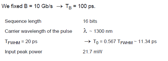
Figure 4 and Figure 5 show the selected fiber parameters.

Figure 4: Nonlinear Dispersive Fiber Main parameters

Figure 5: Nonlinear Dispersive Fiber Dispersions parameters
We will consider SMF with a length of 50 km and losses of 0.4 dB/km.

Note: The effects of group delay and third order of dispersion are not taken into account.
After each fiber, the signal is amplified with SOA. Therefore, LA ~ 50 km. The condition LA < LD is satisfied.
Figure 6 shows the nonlinear parameters.

Figure 6: Nonlinear Dispersive Fiber NonLinear parameters
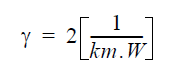
The Kerr nonlinearity coefficient
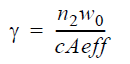
for the fixed values of nonlinear refractive index

will be:
The linear losses for 50 km SMF are 20 dB. This is unsaturated single pass gain required from SOA. To obtain this gain, the following parameters have been used (see Figure 7 and Figure 8).

Figure 7: SOA Main parameters

Figure 8: SOA Physical parameters
The inner losses are 2000[m-1] and the line width enhancement factor = 5. Psat ~ 30 mW and carrier lifetime tC = 200 ps in [1]. Therefore, Esat ~ 6 pJ. Our default values of the SOA component and Γ = 0.25 → Esat ~ 5.2pJ.
Figure 9 shows the initial pattern of pulses, and the same pattern of pulses after 200, 350, and 500 km transmission in SMF and periodic amplification with SOA at every 50 km.

Figure 9: SOA pulse patterns
In this figure, we can see the pattern effect that leads to a reduction in the gain of the pulses after the first one in the first group. Regarding our default parameters, the carrier lifetime is approximately 1.4 ns even for the last pulse, which is at a distance of approximately 1 nm from the first one. There is not enough time for the gain to recover completely.
This lesson demonstrated two basic problems associated with using the SOA as an in-line amplifier:
- pattern effect, which is a consequence of the gain saturation properties of the SOA
- nonlinear crosstalk [3]
References:
[1] M. Settembre, F. Matera, V. Hagele, I. Gabitov, A. W. Mattheus, and S. Turitsyn, “Cascaded optical communication systems with in-line semiconductor optical amplifiers”, Journal of Lightwave Technology, Vol. 15, pp. 962-967, 1997.
[2] F. Matera and M. Settembre, “Study of 1.3 mm transmission systems on standard step-index fibers with semiconductor optical amplifiers”, Optics Communications, Vol. 133, pp.463-470, 1997.
[3] G.P. Agrawal, “Fiber Optic Communication Systems”, 2nd Edition, John Wiley & Sons Inc., 1997.