
When using a directly modulated laser for high-speed transmission systems, the modulation frequency can be no larger than the frequency of the relaxation oscillations. The relaxation oscillation depends on both carrier lifetime and photon lifetime. The approximate expression of this dependence is given by:
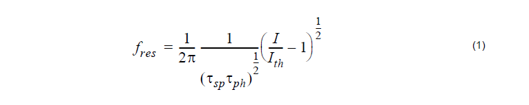
The relaxation oscillation frequency increases with the laser bias current.
In this lesson, we will demonstrate the performance of the high speed system while using the modulation frequency and increasing resonance frequency (through the improvement in the system performance) with the laser bias current. The project is depicted in Figure 1.

Figure 1: Project layout
For the default parameters of our laser rate equation model Ith = 33.45mA,
Tsp = 1ns, Tph = 3ps , and if we assume modulation peak current I = 40mA, and IB = 40mA , the corresponding resonance frequency in accordance with the above equation will be about 1.3 GHz.
Discussion of the numerical parameters: bit rate is 1.3 Gb/s and sequence length 128 bits, therefore, the time window is about 98.5 ns. Samples per bit are 512, therefore, the sample rate is 670 GHz. The default resolution therefore is 10 MHz.
In Figure 2 and Figure 3, the influence of the increased modulation frequency above the resonance one on system performance will be demonstrated. In Figure 2, 1.3 Gb/s (10Gb/s) transmission is studied. The parameters of the laser rate equations are the default ones (I = IB = 40mA) as previously described.

Figure 2: Increase in modulation frequency above resonance
Clearly, modulation with the frequency well above the resonance one leads to unacceptable system performance.
In Figure 3, the influence of the bias current on the resonance frequency, and therefore on system performance, for a fixed bit rate will be demonstrated. We use 1.3 Gb/s transmission, keep all other parameters the same, and use IB = 20mA.

Figure 3: Reduction of bias current
If you compare Figure 3 with Figure 2 (with 1.3 Gb/s transmission and IB = 40mA ),
it is clearly demonstrated that the reduction of the bias current below its threshold
value leads to a decrease in system performance.
In this lesson we have shown the dependence of the performance of the high speed system on the modulation frequency and the laser bias current.
References
[1]G.P. Agrawal, Fiber-Optic Communication Systems, John Wiley & Sons, Inc, second edition, 1997.
[2]G. Keiser, Optical Fiber Communications, McGraw-Hill Higher Education, third edition, 2000.