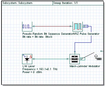
A subsystem is like a component — it has an icon, parameters, and input and output ports. You build a subsystem using a group of components or other subsystems. You can easily create a subsystem by grouping selected components in the layout (see Figure 1).
Subsystems help you to create your own components based on the Component Library without programming, and to organize the layout in different hierarchical levels when there are a large number of components in different levels.
Figure 1: Hierarchical simulation
This lesson describes how to create a subsystem using the External Modulated Laser subsystem from Lesson 1: Transmitter — External modulated laser. You will become familiar with subsystems and the Component Library.
Loading a sample file
To load a sample file, perform the following procedure.
| Step | Action |
| 1 | From the File menu, select Open. |
| 2 | From your C: drive, select Program Files > Optiwave Software > OptiSystem 9 > samples > Introductory tutorials > “Lesson 2 Subsystems – Hierarchical simulation.osd”. |
Creating a subsystem
To create a subsystem, perform the following procedure.
| Step | Action |
| 1 | In the Main layout, select the components that you want to include in the subsystem. A box appears around the selected components (see Figure 2).. |
| 2 | Right-click the selection. A context menu appears (see Figure 24 from Lesson 1). |
| 3 | From the context menu, select Create Subsystem. The subsystem appears in a glass box. When you look inside the subsystem, a subsystem tab appears at the bottom of the Main layout (see Figure 3). Note: The visualizers that are not included in the selection are disconnected. The subsystem does not add additional ports to connect the visualizers. |
Figure 2: Creating a subsystem—Selected components in the Main layout
Looking inside a subsystem
To look inside a subsystem, perform the following procedure.
| Step | Action |
| 1 | Select the subsystem glass box and right-click. A context menu appears (see Figure 3) |
| 2 | From the context menu, select Look Inside. The subsystem opens and a Subsystem tab appears beside the Main layout tab at the bottom of the subsystem layout window (see Figure 3). |
Figure 3: Looking inside a subsystem
| 3 | To return to the Main layout and close the subsystem, right-click in the subsystem layout and select Close Subsystem from the context menu (see Figure 24 from Lesson 1), or To return the Main layout and leave the subsystem open, click the Main Layout tab. |
Creating a subsystem output port
You can change parameters and create ports in order to access the signals from the subsystem.
| Step | Action |
| 1 | Select the subsystem glass box and right-click. A context menu appears. |
| 2 | From the context menu, select Look Inside. The subsystem opens. |
| 3 | From the Layout Tools toolbar, select Draw – Output Port Tool. The cursor changes into a cross-hatch. |
| 4 | Position the cursor on the edge of the subsystem layout where you want to add the output port. The cross-hatch changes into an output port. |
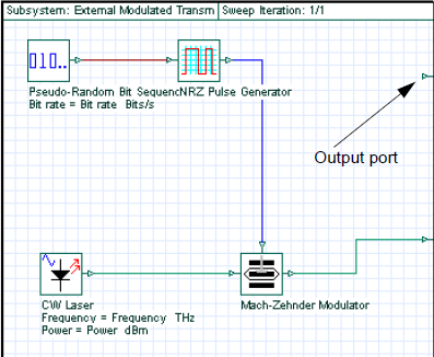
| 5 | Click to place the output port. The output port is created (see Figure 5). |
Connecting a component output port to a subsystem output port
To connect the Mach-Zehnder Modulator output port to the subsystem output port, perform the following procedure.
| Step | Action |
| 1 | From the Layout Tools toolbar, select Layout Tool  . .The cursor changes into the Layout Tool. |
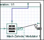
| 2 | Click the Mach-Zehnder output port. The cursor changes into a link (see Figure 4). |
| 3 | To connect the Mach-Zehnder output port to the subsystem output port, drag the cursor from the Mach-Zehnder output port to the subsystem output port (see Figure 5). The output ports are connected. |
| 4 | Click the Main Layout tab to return to the Main layout. The output port appears in the subsystem. Note: Use the same procedure to create input ports. Because this is a transmitter, you will not create input ports in this lesson. |
Figure 4: Link tool in the subsystem
Figure 5: Linking output ports
Changing the port position and location
To change the port position and location, perform the following procedure.
| Step | Action |
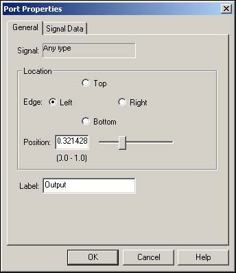
| 1 | In the Main layout, double-click the subsystem port, or In the subsystem, double-click the port. The Port Properties dialog box appears (see Figure 6). |
| 2 | Select the position in the subsystem that you want to move the port to:
• Top |
| 3 | Move the slider to specify the exact position that you want to select. |
| 4 | To return to the Main layout, click OK. |
Figure 6: Port properties
Subsystem properties — name and icon
You can change the name and add an icon for a subsystem by changing the subsystem parameters.
Changing a subsystem name
To change the subsystem name, perform the following procedure.
| Step | Action |
| 1 | In the Main layout, double-click on the subsystem. The Subsystem Properties dialog box appears. |
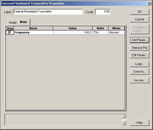
| 2 | In the Label field, type External Modulated Transmitter (see Figure 7). |
| 3 | To return to the Main layout, click OK. The new subsystem name appears below the subsystem glass box and on the subsystem tab (see Figure 8). |
Figure 7: Subsystem properties dialog
Figure 8: Subsystem modified tab name
Adding a subsystem icon
You can load a user-defined image from a file to use as the a subsystem icon.
To add a subsystem icon, perform the following procedure.
| Step | Action |
| 1 | In the Main layout, double-click the External Modulated Transmitter subsystem glass box. The External Modulated Transmitter Properties dialog box appears. |
| 2 | Click the Value cell beside Subsystem Representation. A drop-down list appears. |
| 3 | From the drop-down list, select User Image. |
| 4 | Click the Value cell beside Image Filename, and click The Open dialog box appears (see Figure 9). |
| 5 | Select the image that you want to use as the subsystem icon, and click Open. Note: You can use the image External.bmp in the samples directory. The image you selected appears as the External Modulated Transmitter subsystem icon (see Figure 10). |
| 6 | To return to the Main layout, click OK in the External Modulated Transmitter properties dialog box. |
Figure 9: Subsystem dialog – User icon import
Figure 10: User imported subsystem icon in Project layout
Adding global parameters to a subsystem
In this example, use the External Modulated Transmitter subsystem that you created. To access any parameter inside of the External Modulated Transmitter, look inside of the subsystem.
To change the subsystem component parameter values without looking inside each time you need to access them, you can create global parameters (see Figure 11).
In the following procedures, you will export the Power and Frequency parameters so that you will be able to access them without looking inside the External Modulated Transmitter subsystem.
To add a global parameter to a subsystem, perform the following procedure.
| Step | Action |
| 1 | In the Main layout, double-click External Modulated Transmitter subsystem. The External Modulated Transmitter Properties dialog box appears. |
| 2 | Click Add Param. The Add Parameter dialog box appears (see Figure 11). |
| 3 | Type the following values: • Name: Frequency • Type: floating-point • Category: Main • Minimum value: 100 • Maximum value: 200 • Current value: 193.1 • Units: THz |
| 4 | Click Add. The Frequency parameter is added to the Main category. A message appears in the message window at the bottom of the dialog box to advise you that the Frequency parameter has been added. |
| 5 | Click Add Param. The Add Parameter dialog box appears. |
| 6 | In the Add Parameter dialog box, type the following values: • Name: Power • Type: floating-point • Category: Main • Minimum value: -100 • Maximum value: 30 • Current value: 0 • Units: dBm |
| 7 | Click Add. The Power parameter is added to the Main category. A message appears in the message window at the bottom of the dialog box to advise you that the Power parameter has been added. |
Figure 11: Add Parameter dialog
Figure 12: Frequency parameter added to External Modulated Transmitter
Accessing global parameters
In the last section, you added two parameters to the subsystem. Now you must create a reference between the components inside the subsystem and the global parameters (see Figure 13).
To access global parameters, perform the following procedure.
| Step | Action |
| 1 | Right-click on the External Modulated Transmitter subsystem. A context menu appears. |
| 2 | Select Look inside. The subsystem layout appears. |
| 3 | Double-click the CW Laser. The CW Laser Properties dialog box appears. |
| 4 | Click in the Mode cell beside Frequency and select Script from the drop-down list. |
| 5 | Click in the Units cell beside Frequency and select THz from the drop-down list. |
| 6 | Click the button in the Value cell beside Frequency. The Parameter Script Editor dialog box appears. |
| 7 | Type Frequency and click OK. |
| 8 | Click in the Mode cell beside Power and select Script from the drop-down list. |
| 9 | Click in the Units cell beside Power and select dBm from the drop-down list. |
| 10 | Click the button in the Value cell beside Power. The Parameter Script Editor dialog box appears. |
| 11 | Type Power and click OK. |
| 12 | To return to the subsystem layout, click OK. |
| 13 | To return to the Main layout, click the Main Layout tab. |
Figure 13: Using script parameters
For example, now when you change the value of the Frequency parameter for the External Modulated Transmitter subsystem, you will change the values for the CW Laser inside the External Modulated Transmitter subsystem.
Component Library
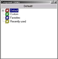
The OptiSystem Component Library consists of four sub-libraries (see Figure 14).
- Default: Read-only — you cannot add or change the parameters of a default component.
- Custom: Allows you to add new components and expand the Component Library. Note: You can base new components on components from the Default library. However, the component name must be different from the name of the component in the Default library. You can also include subsystems in the Custom library.
- Favorites: Allows you to add components to a library that includes the ones you use most frequently.
- Recently used: Components that you have used in recent projects are added automatically to the Recently used library.
Figure 14: Component Library
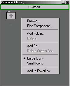
Before you add the External Modulated Transmitter to the Custom library, you will create a new folder named Transmitters (see Figure 15).
Creating sub folders in the Custom Library
To create a a sub folder in the Custom library, perform the following procedure.
| Step | Action |
| 1 | From the Component Library, select Custom. The Custom library opens. |
| 2 | Right-click in the background of the Custom library. A context menu appears (see Figure 15). |
| 3 | Select Add Folder. The New Folder dialog box appears (see Figure 16). |
| 4 | Type Transmitters and click OK. A new folder named Transmitters appears in the Custom library in the Component Library (see Figure 17). |
Figure 15: Creating a custom folder menu
Figure 16: Add Folder dialog
Figure 17: Added folder in Custom library
Adding a component to the library
You can drag components to any folder in the Custom library. To add the External Modulated Transmitter to the Custom library in the Transmitters folder (see Figure 18), perform the following procedure.
| Action | Step |
| 1 | Double-click the Transmitters folder in the Custom library. |
| 2 | In the Main layout, select the External Modulated Transmitter component. |
| 3 | Drag the External Modulated Transmitter subsystem into the Transmitters folder. The External Modulated Transmitter subsystem appears in the Transmitters folder. |
Figure 18: Added component in Custom Library
Creating additional ports
To access the electrical signal from the NRZ Pulse Generator inside the External Modulated Transmitter subsystem, create an additional output port in the subsystem (see Figure 19).
To create a port, perform the following procedure.
| Step | Action |
| 1 | In the Main layout, right-click on the External Modulated Transmitter. A context menu appears. |
| 2 | Select Look Inside. The subsystem layout appears. |
| 3 | Create a new output port in the subsystem (see “Creating a subsystem output port” on page 40). |
Figure 19: Adding a new output port to the subsystem
Adding a fork to the subsystem
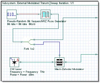
You cannot connect the NRZ Pulse Generator output to this port because it’s already connected to the Mach-Zehnder Modulator input. To solve this problem, you can duplicate the signal from the NRZ Pulse Generator and connect it to both the Mach-Zehnder Modulator input and subsystem output ports by adding a fork (see Figure 20).
To add a fork to the subsystem, perform the following procedure.
Note: To increase the size of the layout, press Ctrl+Shift and drag the cursor from the top left corner of the Main layout to the bottom right corner.
| Step | Action |
| 1 | From the Component Library, select Default > Tools Library. |
| 2 | Drag the Fork 1×2 to the Main layout. |
| 3 | Select the blue connection between the NRZ Pulse Generator and the Mach-Zehnder Modulator. The selected connection changes to red. |
| 4 | Press Delete to delete the connection. |
| 5 | Connect the NRZ Pulse Generator output to the Fork input. |
| 6 | Connect the first Fork output to the subsystem output port. |
| 7 | Connect the second Fork output to the available Mach-Zehnder Modulator input port (see Figure 20). Note: To delete the internal data monitors, from the Layout Tools toolbar select the Monitor tool and click the monitor in each component output port. |
Figure 20: External Modulated Transmitter with two output ports
| 8 | To return to the Main layout, click the Main Layout tab. |
Saving the modified subsystem
To save the modified subsystem, perform the following procedure.
| Step | Action |
| 1 | In the Transmitters folder in the Custom library, select and right-click the External Modulated Transmitter. A context menu appears. |
| 2 | Select Delete. |
| 3 | Drag the modified External Modulated Transmitter from the Main layout into the Transmitters folder in the Custom library. |
Running the External Modulated Transmitter simulation
To run the simulation for the External Modulated Transmitter, perform the following procedure.
Note: Before you run the simulation, you must connect the External Modulated Transmitter output port to a component or visualizer.
| Step | Action |
| 1 | Connect the first External Modulated Transmitter output to the Oscilloscope Visualizer. |
| 2 | Connect the second External Modulated Transmitter output port to the Optical Spectrum Analyzer and to the Optical Time Domain Visualizer. |
| 3 | Run the simulation: a. Click Calculate. b. Click the PLAY button. The results appear in the Calculation Output window. |
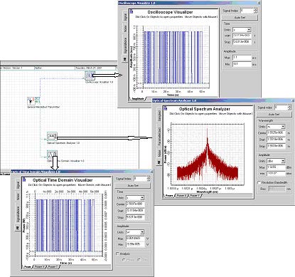
| 4 | To view the graphs of the results, double-click each visualizer (see Figure 21).Note: The center frequency and power of the transmitter are defined by the values of the Frequency and Power parameters. |
Figure 21: Results from External Modulated Transmitter


