Inter-channel cross-talk can arise from a variety of sources. These sources may include [1]:
- An optical filter or ADM that selects one channel (drop) and passes others over the network
- An optical switch switching between different wavelengths creates cross-talk from the imperfect isolation between the switch ports
- Other cross-talk types include amplifier induced, router induced, and XPM induced
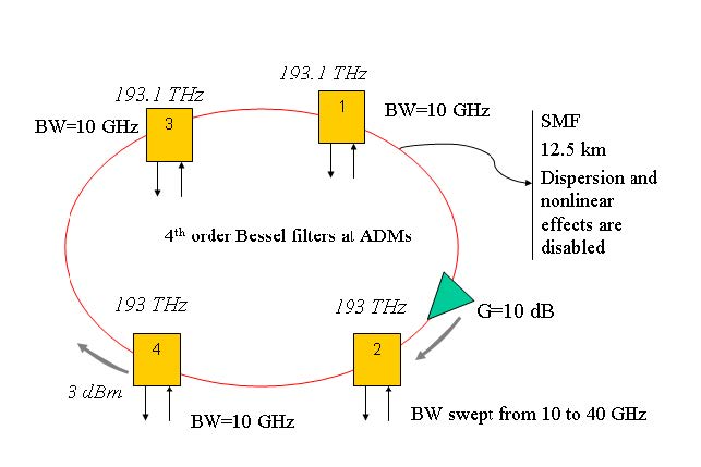
A particular signal can accumulate cross-talk from different elements and channels over the network. Cross-talk can be reduced by using several techniques such as wavelength dilation or filter cascading. In this example, we will investigate the effect of interchannel cross-talk at ADM to a ring network. The project is found in the Interchannel crosstalk at ADM in a ring network.osd file. This network contains 4 nodes that communicate over two channels at 193 THz and 193.1 THz, as shown in Figure 1. The bit rate is 10 Gbps. ADMs at each node is modeled by using WDM add and WDM drop components. WDM add and drop components are created by using 4th order Bessel filters. The ring is ended with a ring control component which can circulate the signals around ring for a given number of times. The distance between nodes is 12.5 km and we inserted an ideal amplifier just before node 2 to compensate for the total fiber loss in the ring. Dispersion and nonlinear effects of fibers are disabled to isolate the crosstalk effect.
Figure 1: A basic ring network with 4 nodes
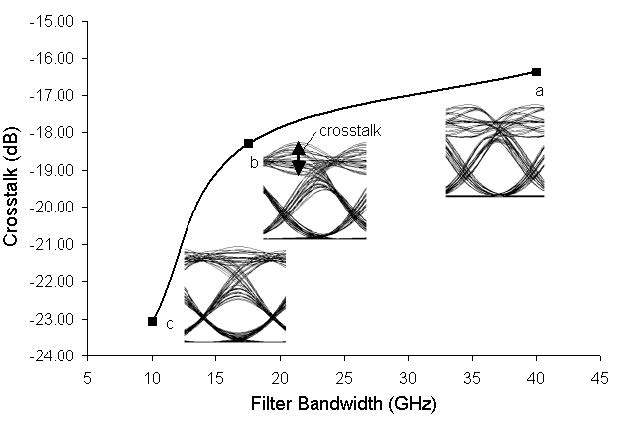
To show the effect of interchannel cross-talk, we have swept the band width of the filters in ADM of node 2 from 10 to 40 GHz. The eye diagrams at node 2 for several bandwidths are given in Figure 2. This figure also shows the cross-talk [1], [2], and [3], as defined 10log(Vxt/Vsig) versus filter bandwidth.
Figure 2: Cross talk versus filter bandwidth at node 2. Insets show the eye diagrams when filter bandwidth is a) 40 GHz, b) 17.5 GHz, and c) 10 GHz.
References:
[1] G. P. Agrawal, Fiber Optic Communication Systems, Wiley-Interscience, 1997.
[2] Tim Gyselings et. al, “Crosstalk analysis of multi-wavelength optical cross connects”, J. Light. Tech. 17, pp. 1273, 1999.
[3] R. Ramaswami and K. N. Sivarajan, Optical Networks: A practical Perspective, Morgan Kaufmann, 1998.


