
The objective of this lesson is to demonstrate the relation between the voltage applied to the modulator arms and the chirp in the output for MZ Lithium Niobate modulators.
Chirp is a critical element in high bit rate lightwave systems because it can interfere in the limit of the system distance [1]. External modulators offer a way to reduce or eliminate chirp because the laser source is held in the narrow linewidth, steady-state mode. External modulator is typically either a LiNbO3 modulator or an electroabsorptive modulator. In this lesson the chirp induced by the LiNbO3 is analyzed based on the voltage of operation.
Here the modulator is analyzed in a dual-drive design shown in Figure 1 (where ΔV1 = –ΔV2).

Figure 1: Dual-drive system layout
The modulator is operating in the quadrature mode. This means that the bias voltage places the modulator at the midpoint of the optical response curve, and therefore, the intensity is at half of its peak value. Figure 2 shows the parameters utilized to setup the modulator. The extinction ratio is set to 200dB to avoid any chirp caused by asymmetric Y-branch waveguides [2]. The modulator is set to work in a non-normalized way, which means the electrical input signal will not be normalized.
In accordance with [3], for a dual-drive modulator with geometry that is exactly the same for both arms. The chirp is given in terms of driving voltages:
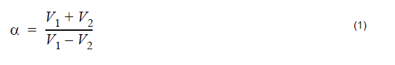
where V1 and V2 are the voltage applied to arm 1 and 2, respectively.

Figure 2: Parameters setup for the modulator operating in the “quadrature” point
In agreement with Equation 1, to achieve zero chirp from the modulator, the relation
between the voltages applied has to be V1 = -V2 . Figure 3 shows the voltages at
port 2 and 3 for a determined sequence of pulses.
 V1pp = 2.0V, and Input port 3 (b) V2pp = 2.0V to achieve a near zero chirp from the modulator")
 V1pp = 2.0V, and Input port 3 (b) V2pp = 2.0V to achieve a near zero chirp from the modulator")
Figure 3: Electrical signal at Input Port 2 (a) V1pp = 2.0V, and Input port 3 (b) V2pp = 2.0V to achieve a near zero chirp from the modulator
The results achieved for these voltages is shown in Figure 4. The amplitude of the optical signal varies from 0 to 1mW. The amplitude of the chirp is around 100 Hz (it could be considered practically zero due its small value).

Figure 4: Optical signal at the modulator output
To show the difference in the value of chirp with changes in the voltage applied, the
peak-to-peak voltages are set to V1pp = 3.0V, V2pp = 1.0V , to give α = 0.5.
Figure 5 shows the electrical input signals.
 and Input port 3 (b) to achieve a 0.5 from the modulator")
 and Input port 3 (b) to achieve a 0.5 from the modulator")
Figure 5: Electrical signal at Input Port 2 (a) and Input port 3 (b) to achieve a α = 0.5 from the modulator
The chirp achieved is shown in Figure 6. The optical signal seems the same, however, the chirp in the signal is much larger than that presented in Figure 4. The amplitude of the chirp is around 3 GHz.

Figure 6: Optical signal at the modulator output for α = 0.5
For α = -0.5 , the peak-to-peak voltages are set to V1pp = 1.0V, V2pp = 3.0V. The result is shown in Figure 7.

Figure 7: Optical signal at the modulator output for α = 0.5
As demonstrated in this lesson the chirp at the output signal, in the Mach-zehnder modulator, can be controlled by adjusting the voltages applied in the arms of the modulator. More information about chirp in Mach-Zehnder modulators can be found in the references.
References:
[1]Cartledge, J.C.; Rolland, C.; Lemerle, S.; Solheim, A., “Theoretical performance of 10 Gb/s lightwave systems using a III-V semiconductor Mach-Zehnder modulator. IEEE Photonics Technology Letters, Volume: 6 Issue: 2, Feb. 1994, Page(s): 282 -284.
[2]Cartledge, J.C., “Performance of 10 Gb/s lightwave systems based on lithium niobate Mach-Zehnder modulators with asymmetric Y-branch waveguides”. IEEE Photonics Technology Letters, Volume: 7 Issue: 9, Sept. 1995, Page(s): 1090 -1092.
[3]AT&T microelectronics. “The Relationship between Chirp and Voltage for the AT&T Mach-Zehnder Lithium Niobate Modulators”. Technical Note, October 1995.