Modified Duobinary Transmitter

Project MODB_ModulationSystem.osd (Figure 1) demonstrates a system that is an is optical modified duobinary RZ transmission system, which is equivalent to a duobinary carrier suppressed. Figure 1 – Modified duobinary system
Interferometer Characterization
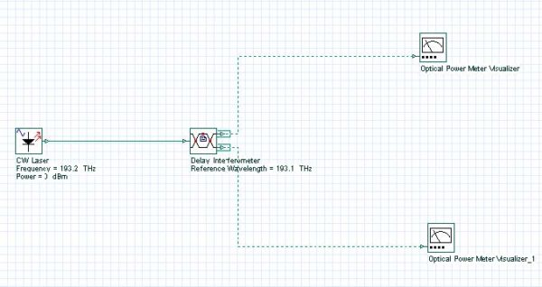
The objective of this lesson is to demonstrate the response of the delay interferometer when the wavelength and polarization of the input signal changes. The objective of this lesson is to demonstrate the response of the delay interferometer when the wavelength and polarization of the input signal changes. Figure 1 shows the system layout designed.…
Fundamental and Higher Order Solitons
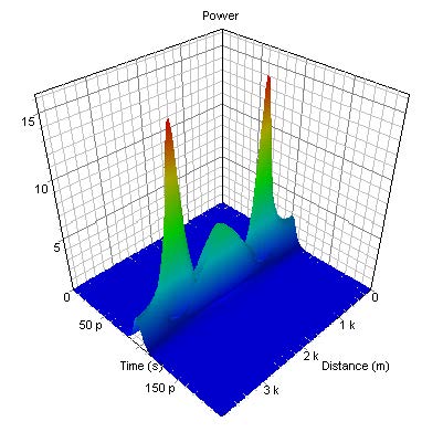
This lesson demonstrates that the exact balance between the effects of SPM and GVD leads to the formation of a fundamental soliton – a light pulse that propagates without changing its shape and spectrum, and shows some basic features of the higher-order solitons. Figure 1 shows the layout and its global parameters. Figure 1: System…
Interactions of Optical Solitons
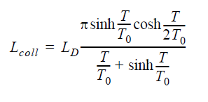
This lesson demonstrates the particle-like nature of the solitons through some basic features of their interactions. The fundamental optical soliton propagates (see “Self-phase modulation and group velocity dispersion” from the Tutorials) undistorted due to the exact balance between the nonlinear (SPM) and dispersive (GVD) effects. Thus the soliton propagates as a “particle” (i.e. maintains its…
Decay of Higher Order Solitons in the Presence of Third-Order Dispersion
![Optical System - Figure 7 - Output pulse shape after 11.6 km (or 5 soliton periods) of propagation. Second order soliton has been split into its constituents by the effect of TOD [1]](https://optiwave.com/wp-content/uploads/2013/06/Optical-System-Output-pulse-shape-after-11.6-km-or-5-soliton-periods-of-propagation.-Second-order-soliton-has-been-split-into-its-constituents-by-the-effect-of-TOD-1.jpg)
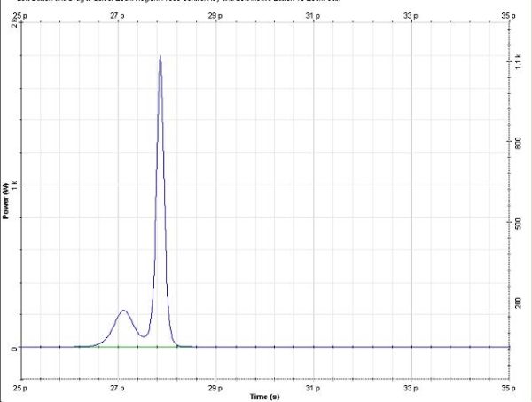
This lesson demonstrates the effect of third-order dispersion on the fundamental and higher-order solitons. The layout that we use and its global parameters are shown in Figure 1. Figure 1: System layout with parameters The setups for the bit sequence generator and for the sech-pulse generators are displayed in Figure 2 and Figure 3. Figure…
Decay of Higher Order Solitons in the Presence of Intrapulse Raman Scattering
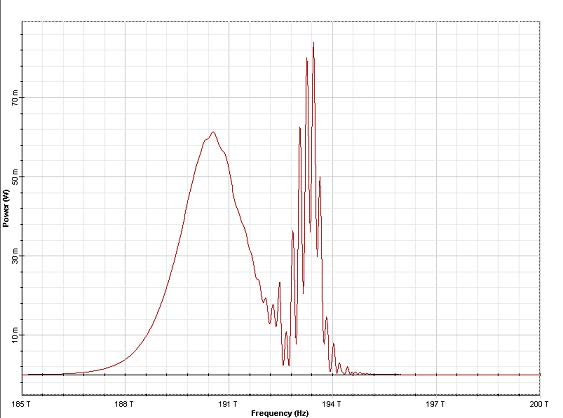
This lesson demonstrates the influence of stimulated Raman scattering on short soliton pulses. The layout and its global parameters are shown in Figure 1. Figure 1: Layout and global parameters Figure 2: Setup for the Bit sequence generator Figure 3: Setups for the Sech-pulse generator The parameters of the nonlinear dispersive fiber component are shown…
Decay of Higher Order Solitons in the Presence of Self-Steepening
This lesson demonstrates the influence of self-steepening effect on short soliton pulses and to compare it with that of the intrapulse Raman scattering. The layout and global parameters are shown in Figure 1. Figure 1: Layout and parameters The setups for the Bit sequence generator and the sech-pulse generator are shown in figures 2 and…
Stability of solitons in birefringent optical fibers
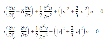
This lesson demonstrates that the Kerr nonlinearity, which stabilizes solitons against spreading due to GVD, also stabilizes them against splitting due to birefringence [1] – [3]. The “single-mode” fibers are actually bimodal because of the presence of birefringence. This means that the group velocity is different for pulses polarized along the two principal axes. If…
Orthogonal Raman gain
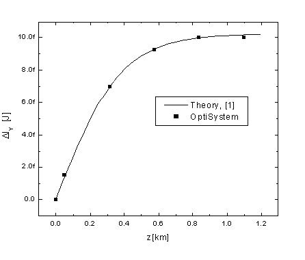
This lesson demonstrates the energy exchange between two optical solitons with orthogonal polarizations associated with the orthogonal Raman gain [1]. Using equations (17a) from the technical description of the Nonlinear dispersive fiber component it can be shown [1] that the energy exchange between two solitons: where P1 > > P2 and Δ ω > 0…
Average Soliton Regime
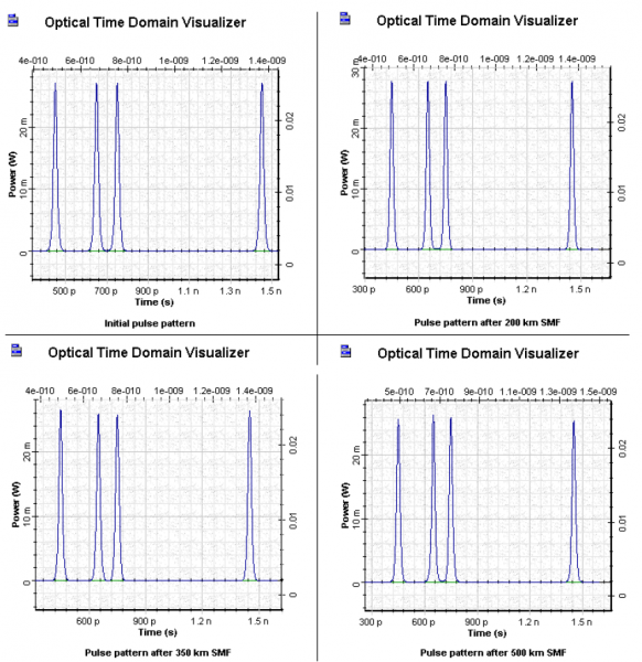
This lesson demonstrates the average soliton regime at 10 Gb/s transmission over a 500 km optical link consisting of SMF. Figure 1 shows the layout that was used. Figure 1: Average soliton regime layout Figure 2 shows the global and pulse parameters used to achieve transmission at 10 Gb/s. Figure 2: Simulation and Main parameters…
SOA as In-line Amplifier in Soliton Communication Systems
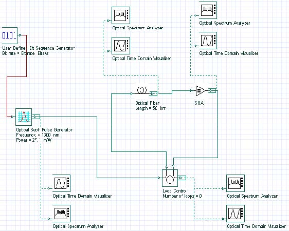
One possible way to upgrade an existing network from previously installed standard optical fibers is to exploit the 1.3 mm optical window, where the step index fibers have a zero-dispersion wavelength using SOA. The advantages of using SOA as in-line single-channel optical amplifiers are: low dispersion of the SMF at this carrier wavelength attractive features…
Power Level Management in Optical Metro Networks
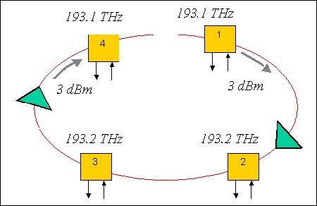
Design without amplification In this example, our goal is to design a basic transparent ring network without amplification and discover the power related issues. Metro networks using ring topology are expected to have more dynamic traffic patterns compared to most long-haul networks. They are also expected to have optically transparent nodes with a minimum number…
Migrating to 10Gbps in Metro Networks
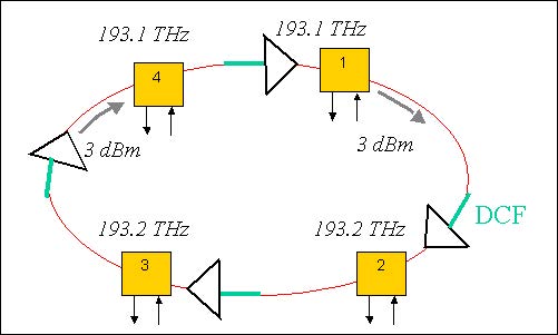
In this example, we will investigate the issues at high data bit rate, particularly 10 Gbps (OC-192) systems in metro area ring networks. At higher bit rates, in addition to loss compensation, we may also need to consider the chromatic dispersion compensation. Different options related to dispersion and initial chirp will be investigated. For this…
Negative Dispersion Fiber for Metro Networks
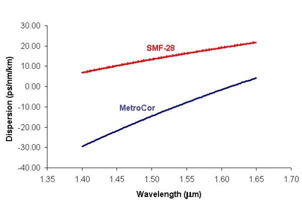
In this example, we compare two types of fibers, Corning’s MetroCor and SMF-28 fibers for metro network applications. MetroCor Fiber has a negative dispersion, whereas SMF-28 has a positive dispersion in the EDFA bands. Dispersion characteristics of these two fibers are shown in Figure 1. For metro applications, directly modulated lasers (DMLs) are preferred because…
Interchannel Crosstalk in Metro Networks
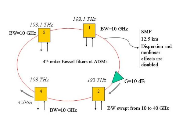
A particular signal can accumulate cross-talk from different elements and channels over the network. Cross-talk can be reduced by using several techniques such as wavelength dilation or filter cascading. In this example, we will investigate the effect of interchannel cross-talk at ADM to a ring network.

