Apodized Fiber Bragg Grating Simulation
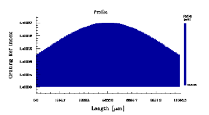
Reference T. Erdogan, ‘Fiber Grating Spectra,’ J. Lightwave Technol., vol.15, No.8, (1997), pp.1277-1294. Description The example demonstrates the effect of apodization on the optical properties of a fiber grating. A chirpless, sinusoidal Bragg grating has a user-defined average refractive index and apodization. The average index is modulated by the Gaussian function: Index_Mod*exp(-ln2*(2*(x-Length/2)/Length)^2) The fiber Bragg grating…
Sampled Grating
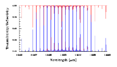
Reference T. Erdogan, ‘Fiber Grating Spectra,’ J. Lightwave Technol., vol.15, No.8, pp.1277- 1294, (1997). Description The example demonstrates a sampled grating exhibiting periodic superstructure. The superstructure is a collection of 99 identical gratings and phase shift blocks. The gratings are uniform and have a uniform average index. The main result is the multi-peak, periodic superstructure…
Mode Conversion by Fiber Bragg Grating
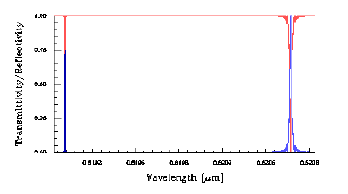
Reference C.-X. Shi and T. Okoshi, ‘Mode conversion based on the periodic coupling by a reflective fiber grating,’ Opt. Lett., vol.17, No.23, pp.1655-1657, (1992). Description The example demonstrates the mode conversion between the LP01 and LP02 mode in a fiber with Bragg grating. The fiber has four LP core modes. In the example, only three…
Phase-shifted Bragg Grating Filter Based on Planar Waveguide
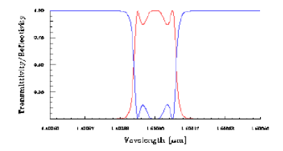
Reference R. Zengerle and O. Leminger, ‘Phase-shifted Bragg-grating filters with improved transmission characteristics,’ J. Lightwave Technol., vol. 13, No.12, (1995), pp. 2354- 2358. Description The example demonstrates an InP/InGaAsP planar waveguide filter. The design is based on five gratings and four phase shifts. The uniform, rectangular-shaped gratings are placed on the top of the waveguide.…
Long-period Fiber Grating for Gain Flattening
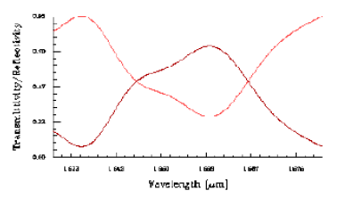
Reference A. M. Vengsarkar et al., ‘Long-period fiber-grating-based gain equalizers,’ Opt. Lett., vol.21, No.5, (1996), pp.336-338. Description The example demonstrates a fiber grating filter used to equalize the gain of a fiber amplifier. The LP01 fiber core mode is coupled to the LP08 cladding mode. A twograting structure is present in the fiber. The gratings…
Pulse Reshaping by Uniform Fiber Grating
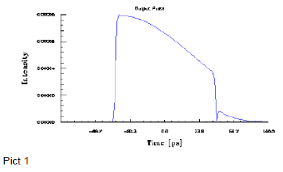
Reference L. R. Chen et. al., ‘Ultrashort pulse reflection from fiber gratings: A numerical investigation,’ J. Lightwave Technol., vol.15, No.8, (1997), pp.1505-1512. Description The example demonstrates a transform-limited Gaussian pulse reflected from uniform fiber gratings. The gratings have different index modulation values. You can change the grating modulation index and compare the calculated results with…
Pulse Reshaping by Apodized Fiber Gratings
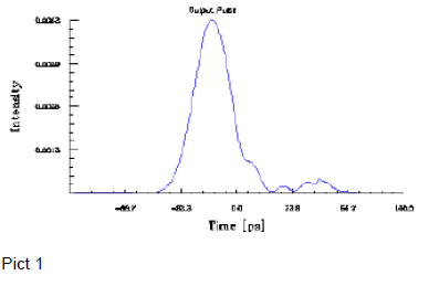
Reference L. R. Chen et. al., ‘Ultrashort pulse reflection from fiber gratings: A numerical investigation,’ J. Lightwave Technol., vol.15, No.8, (1997), pp.1505-1512. Description The example demonstrates a transform-limited Gaussian pulse reflected from apodized fiber gratings. The gratings are apodized by a Gaussian function and the same index modulation value of 4.356e-4. You can change the…
In-Fiber Moiré Gratings
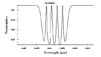
Reference L. A. Everall et al, ‘Multiple-passband in-fiber Moiré resonators fabrication using nearfield holography with a chirped phase mask,’ Proc. of the 11th Int. Conf. on Integrated Optics and Optical Fiber Communications and 23rd European Conference on Optical Communications, IOOC/ECOC ’97, Edinburgh, 22-25 September 1997, vol.2, pp.41- 44. Description The example demonstrates how to simulate…
Synthesis of a Filter with User-Defined Spectrum
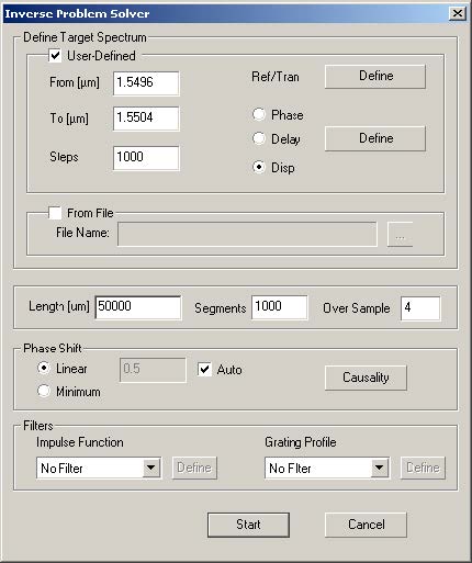
In this lesson we show an example of the synthesis of a filter with an arbitrary user defined spectrum. In this example, we ask for a bandpass filter having a reflection coefficient with a linear variation of amplitude (the reflectivity has a square root variation). Step 1 1 Choose File > New > Single Fiber.…
Synthesis of a Grating for Dispersion Compensation
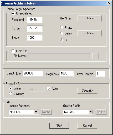
Step 1 1 Open a new project with File > New > Single Fiber. 2 Choose Calculation > Inverse Scattering Solver to get the Inverse Problem Solver dialog box. 3 Set the From and To wavelength fields to 1.5498 and 1.5502. 4 Set the grating length at 20 cm in the Length field. 5 Click on…
Lesson 6 – Reconstruction of Unknown Grating
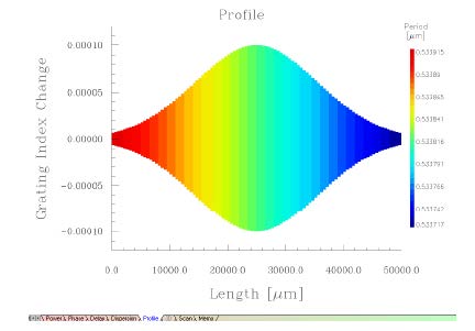
In this lesson we check that the layer peeling algorithm can reconstruct an unknown grating with knowledge of only the reflection coefficient. In the first step, we select a typical grating with chirp and apodization and calculate its reflection coefficient. This spectrum is then exported to a text file. In the next step, OptiGrating is…
Synthesis of a Band Pass Filter
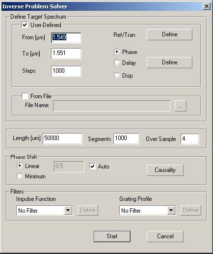
Step 1 1 Open a new project with File > New > Single Fiber. 2 Calculation > Inverse Scattering Solver, to get Inverse Problem Solver dialog box. 3 Select User Defined frame checkbox. 4 Enter the starting and ending wavelengths, and the number of steps in the User-Defined frame as shown. The Steps field indicates the number…
Parameter Scan
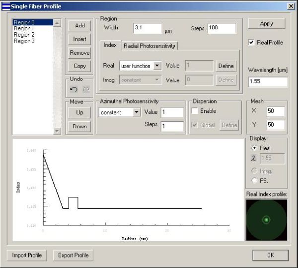
In OptiGrating, all the parameters related to the grating can be scanned with the Parameter Scan tool. It can help the user find optimized grating parameters to meet the application requirements. In this lesson, we will simulate a grating, which has a higher order Gaussian apodization profile. The FWHM of the grating apodization function will…
Material Dispersion

Step 1 In this step, you will create a new project. Choose the Single Fiber Module, and define fiber parameters. To define fiber parameters 1 On the Toolbar, click the New button. 2 In the New dialog box, click Single Fiber. 3 In the Project Window, click the Fiber/Waveguides Parameters button. 4 In the Single…
Lesson 2 – Sensors
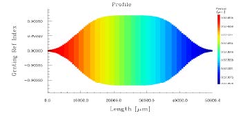
In this lesson, you will use the Fiber Bragg Grating example from Lesson 1. Have a look at the Profile graph. Step 1 In this step, you will learn to define Sensor characteristics. To define Sensor characteristics 1 Select Grating from the Parameters menu, or simply select the Grating icon on the left. 2 In…

