
Step 1
In this step, you will create a new project. Choose the Single Fiber Module, and define
fiber parameters.
To define fiber parameters
| 1 | On the Toolbar, click the New button. |
| 2 | In the New dialog box, click Single Fiber.
|
| 3 | In the Project Window, click the Fiber/Waveguides Parameters button. |
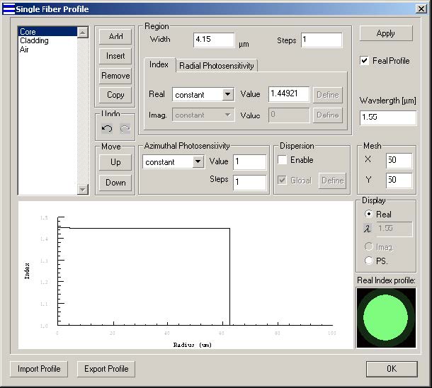
| 4 | In the Single Fiber Profile dialog box, add three regions: Core, Cladding, and Air. Note: The name of the region can be edited by double clicking on it. |

For Core, enter the following data:
Width: 4.15
Real Index: constant
Value: 1.44921
For Cladding, enter the following data:
Width: 58.35
Real Index: constant
Value: 1.44403
For Air, enter the following data:
width: 20
Real Index: constant
Value: 1.0
Step 2
In this step, you will define the material dispersion of the fiber core.
To define the material dispersion of the fiber core
| 1 | In the Single Fiber Profile dialog box, Select the Enable and deselect the Global options in the dispersion section. |
| 2 | Highlight the core region, and select Define in the dispersion section. |
| 3 | In the Material dispersion dialog box, select Define in the Host section. |
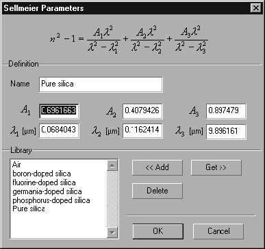
| 4 | In the Sellmeier Parameters dialog box, select Pure Silica from the library and press Get, followed by pressing OK to close the Sellmeier Parameters dialog box. You can see in the Material Dispersion dialog box that the host material is now Pure Silica. |
| 5 | Similarly as in the previous step, define germanium-doped silica for the Dopant+ material |
| 6 | Similarly as in the previous step, define fluorine-doped silica for the Dopantmaterial |
Your Material dispersion dialog box should look like this:
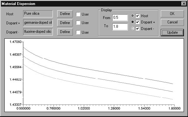
| 7 | Press OK in the Material Dispersion dialog box to close it. |
To open the Sellmeier Coefficients dialog box
| 1 | In the Dispersion box, click the Define button. |
| 2 | In the Material Dispersion dialog box, select Define in the Host section. |
| 3 | In the Sellmeier Coefficients dialog box, highlight the Pure silica material and press the Get button. The Sellmeier coefficients in the dialog box are replaced by the Sellmeier coefficients of Pure silica |
| 4 | Click the OK button to close the Sellmeier Parameters dialog box. |
Note: The Sellmeier Coefficients Library is a separate file and is common for all
projects.
- You can add recently entered coefficients to the library, or you can get previously added coefficients from the library.
- Instead of writing new coefficients, all you need to do is double-click on a desired material in the library.
Step 4
In this step, you will define the material dispersion of the fiber cladding and Air.
To define the material dispersion of the fiber cladding
| 1 | Highlight the Cladding region, and select Define in the dispersion section |
| 2 | In the Material dispersion dialog box, select Define in the Host section. |
| 3 | In the Sellmeier Parameters dialog box, select Pure Silica from the library and press Get, followed by pressing OK to close the Sellmeier Parameters dialog box. You can see in the Material Dispersion dialog box that the host material is now Pure Silica. |
| 4 | Similarly as in the previous step, define germanium-doped silica for the Dopant+ material |
| 5 | Similarly as in the previous step, define fluorine-doped silica for the Dopantmaterial |
| 6 | Press OK in the Material Dispersion dialog box to close it. |
To define the material dispersion of the Air
| 1 | Highlight the Air region, and select Define in the dispersion section |
| 2 | In the Material dispersion dialog box, select Define in the Host section. |
| 3 | In the Sellmeier Parameters dialog box, select Air from the library and press Get, followed by Pressing OK to close the Sellmeier Parameters dialog box. You can see in the Material Dispersion dialog box that the host material is now Air. |
| 4 | Press OK in the Material Dispersion dialog box to close it. |
Note: Dopant settings have no effect for Air
Step 5
In this step, you will select fiber modes in the Single Fiber Modes dialog box.
To select modes
| 1 | From the Parameters Menu, click Mode…to open the Single Fiber Modes (multiple modes) dialog box. Here, you will see the calculated modes for the fiber defined in the previous steps. |
| 2 | In the Single Fiber Modes dialog box, select the first six modes. To do this, click the first mode, press down the SHIFT key, and click the sixth mode. |
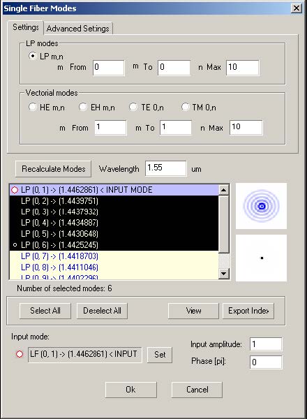
| 3 | Click the OK button. |
Note: In the Single Fiber Modes dialog box, you can select multiple modes.
Step 6
In this step, you will define the grating parameters.
To define the grating parameters
| 1 | In the Project Window, click the Grating Parameters button. |
| 2 | In the Grating Manager dialog box, double-click the listed grating to open the Grating Definition dialog box. |
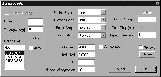
| 3 | In the grating Definition dialog box, disable the Auto check box. |
| 4 | In the Period box, type 450. |
| 5 | From the Apodization list box choose Gaussian and in the Taper’s parameter box type 1. |
| 6 | In the Length box, type 40000. |
| 7 | In the Ind. Mod. box, type 0.0002. |
| 8 | In the Number Of Segment box, type 101. |
| 9 | Click the OK button to close the Grating Definition dialog box, and then click OK to close the Grating Manager dialog box. |
Note: The grating parameters are described in detail in the “Technical
Background” section.
Step 7
In this step, you will perform a Spectrum calculation and see the final result of all your
efforts.
To do the calculation
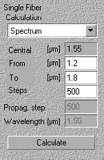
| 1 | In the Project Window, from the Calculation list box, select Spectrum.
|
| 2 | In the From box, type 1.2 to set the beginning point of the calculation range. |
| 3 | In the To box, type 1.8 to set the end point of the calculation range. |
| 4 | In the Steps box, type 500 to assign many points for calculation. |
| 5 | Go to Parameters > Dispersion. Make sure the Dispersion option is checked in the Parameters drop down box. |
| 6 | Click the Calculate button. |
When the Power tab is enabled and you select only the leftmost red graph button,
your graph should look like this:
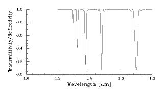
The graph shows the wavelengths for which the grating with period 450 μm will
transfer the incident mode’s power to the other five modes.