
Material Loss dialog box
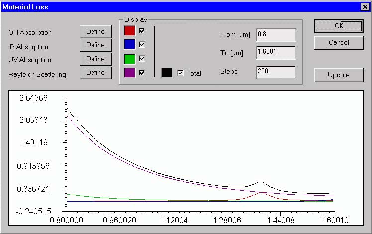
The “Material Loss” dialog box allows you to define parameters for the material loss
models and preview them on the attached display. The material loss includes the OH
radicals, infrared, and ultraviolet absorption models, as well as the Rayleigh
scattering model.
To access this dialog box, do the following steps:
| Step | Action |
| 1 | Open the “Properties of Fundamental Mode” dialog box |
| 2 | Check the “Material Loss” option |
| 3 | Press the “Define” button for the “Material Loss” option, or |
| 4 | Access it by double-clicking in the “Material Loss” view tab. |
 The elements and controls of the “Material Loss” dialog box are described below.
Define
You can define the hydroxyl (OH), infrared (IR), ultraviolet (UV) absorption
parameters, and the Rayleigh scattering parameters by pressing the “Define” buttons
corresponding to each of the loss listing. If the “User” box is cleared, then the program displays a loss model dialog box that corresponds to the current option. If the “User”
box is checked, the program launches the “User Defined Function” dialog box, where you can define custom models.
Display
You can select the wavelength range for the material loss display and toggle between
displaying different curves.
Update
By pressing the Update button, you can refresh the display after recent changes.
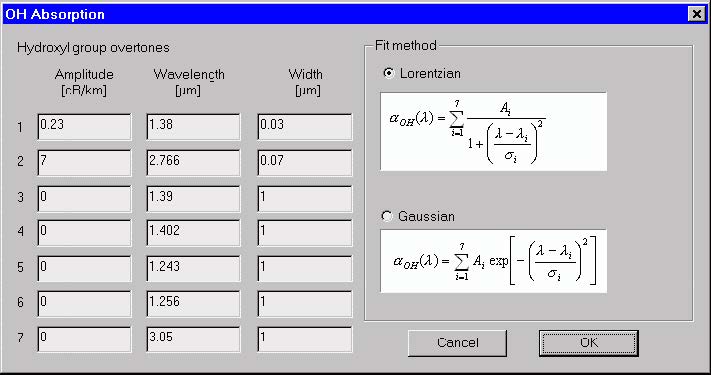
OH Absorption dialog box
The “OH Absorption” dialog box allows you to define the hydroxyl group absorption
characteristics. The characteristics are defined by fitting to the OH overtone
resonance curves. You can form the absorption curve either by adding Lorentzian or
Gaussian shaped resonance.
 To access this dialog box, do the following steps:
| Step | Action |
| 1 | Open the “Properties of Fundamental Mode” dialog box |
| 2 | Check the “Material Loss” option |
| 3 | Press the “Define” button for the “Material Loss” option |
| 4 | Press the “Define” button for the “OH Absorption option” , or |
| 5 | Access it by double-clicking in the “Material Loss” view tab. |
The elements and controls of the “OH Absorption” dialog box are described below.
Hydroxyl Group Overtones
The Hydroxyl Group Overtones section refers to resonance in the absorption spectra
caused by the presence of OH impurities in the fiber material. The OH absorption
curve is composed of a series of independent resonance characteristics that are
added together. You can create up to seven resonance by providing their amplitudes,
central wavelengths, and widths.
Fit Method
The particular resonance may be modeled by Lorentzian or Gaussian curves. You
select one or the other as the OH absorption fitting model. Formulas for both fitting
methods are displayed in the dialog box
See also the “OH-Radical Absorption Model” section in the “Technical Background”.
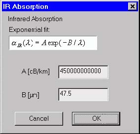
IR Absorption dialog box
The “IR Absorption” dialog box allows you to define the parameters of an
experimental-fit model of infrared absorption. The experimental fit is based on the
exponential curve with two parameters.
To access this dialog box, do the following steps:
| Step | Action |
| 1 | Open the “Properties of Fundamental Mode” dialog box |
| 2 | Check the “Material Loss” option |
| 3 | Press the “Define button” for the “Material Loss” option |
| 4 | Press the “Define” button for the “IR Absorption” option, or |
| 5 | Access it by double-clicking in the “Material Loss” view tab. |
 The elements and controls of the “IR Absorption” dialog box are described below.
A
Enter the amplitude of the exponential fit curve.
B
Enter the exponential 1/wavelength decay coefficient.
See also the “Infrared Absorption Model” section in the “Technical Background”.
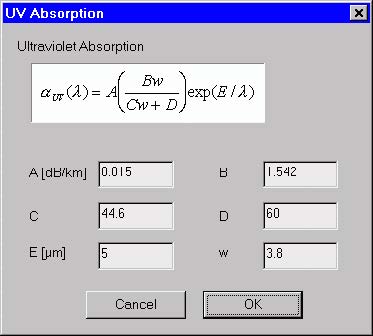
UV Absorption dialog box
The “UV Absorption” dialog box allows you to define the parameters of an
experimental-fit model of ultraviolet absorption. The fit is based on the exponential
curve with six parameters.
To access this dialog box, do the following steps:
| Step | Action |
| 1 | Open the “Properties of Fundamental Mode” dialog box |
| 2 | Check the “Material Loss” option |
| 3 | Press the “Define” button for the “Material Loss” option |
| 4 | Press the “Define” button for the “UV Absorption” option, or |
| 5 | Access it by double-clicking in the “Material Loss” view tab. |
 The elements and controls of the “UV Absorption” dialog box options are described
below.
A
Enter the amplitude of the exponential fit curve.
B, C, D
Enter the B, C, and D coefficients of the fit curve.
E
Enter the 1/wavelength decay coefficient of the fit curve.
w
Enter the mole fraction of the impurity.
See also the “Ultraviolet Absorption Model” section in the “Technical Background”.
Rayleigh Scattering dialog box
The “Rayleigh Scattering” dialog box allows you to define the parameters of an
experimental-fit model of Rayleigh scattering in fibers. The fit is based on the typical
inverse wavelength dependence of the small dipole scattering.
To access this dialog box, do the following steps:
| Step | Action |
| 1 | Open the “Properties of Fundamental Mode” dialog box |
| 2 | Check the “Material Loss” option |
| 3 | Press the “Define” button for the “Material Loss” option |
| 4 | Press the “Define” button for the “Rayleigh Scattering” option, or |
| 5 | Access it by double-clicking in the “Material Loss” view tab. |
 The elements and controls of the “Rayleigh Scattering” dialog box options are
described below.
A
You can adjust only one number, the scattering amplitude A, to fit the Rayleigh
scattering curve.
See also the “Rayleigh Scattering Model” section in the “Technical Background”.
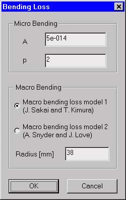
Bending Loss dialog box
The “Bending Loss” dialog box allows you to define parameters for the microbending
and macrobending loss models.
To access this dialog box, do the following steps:
| Step | Action |
| 1 | Open the “Properties of Fundamental Mode” dialog box |
| 2 | Check the “Material Loss” option |
| 3 | Press the “Define” button for the “Bending Loss” option |
 The elements and controls of the “Bending Loss” dialog box options are described
below.
Microbending
In the microbending loss model, A is an arbitrary fit constant and p is the power
coefficient. Typical values for A are much smaller than 1, while typical p is about 2.
Macrobending
In the macrobending loss model you can only select the bend radius. An alternative
choice between two models is allowed if the selected mode id the fundamental one.
See also the “Macrobending Loss Model” and “Microbending Loss Model” sections in
the “Technical Background”.
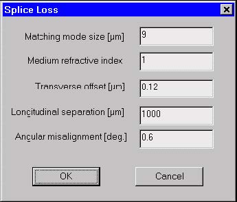
Splice Loss dialog box
The “Splice Loss” dialog box allows you to define parameters for the splice loss
model. The model is based on a formula derived for the case of two glass rods with
approximate Gaussian modes. The rods represent cores of two spliced fibers, while
the finite cladding dimension is ignored – it is assumed that the core rods are in an
infinite cladding medium.
To access this dialog box, do the following steps:
| Step | Action |
| 1 | Open the “Properties of Fundamental Mode” dialog box |
| 2 | Check the “Material Loss” option |
| 3 | Press the “Define” button for the “Splice Loss” option |
 The elements and controls of the “Splice Loss” dialog box options are described
below.
Matching Mode Size
Enter the mode size of the other fiber that would be spliced with the fiber under
design.
Medium Refractive Index
Enter the common cladding index of the fibers.
Transverse Offset
Enter the transverse offset between the two fibers’ axes.
Longitudinal separation
Enter the longitudinal separation gap between the two fibers.
Angular Misalignment
Enter the angular tilt between the two fibers.
See also the “Splice Loss Model” section in the “Technical Background”.