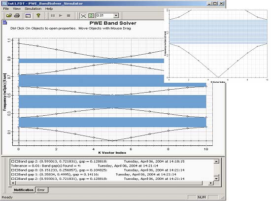
When finished with editing band solver parameters click Run… to start the simulations. A simulation window will be launched and simulation starts. You will be notified in the output window at the bottom (Notification tab) about progress of the simulations. After the simulation is finished the graph is populated with set of eigenfrequencies of individual k-vectors. By default no processing is applied to the output data and the normalized frequencies are displayed as an unconnected set of points.
Figure 5: Band structure of the Bragg grating with layers of equal thickness 0.5mm (permittivity 13.0/1.0)
Use the Connect button on the Diagram toolbar to connect the eigenfrequencies of individual bands to get clearer picture of the band diagram. On occasions the current version of the engine will calculate the eigenvalues not in an exact order, in which case the connect button will produce incorrect band diagram. You can zoom on the diagram by right clicking and selecting the zoom tool. To identify the band gaps, if present, use the Locate band gaps button on the Diagram toolbar. It is possible to set a tolerance for the bandgaps detection in the adjacent input field. By default the tolerance is set to 0.01. Setting a high tolerance you can get rid of the highlighted band gaps.


