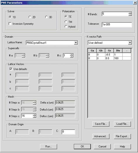
Open PWE Parameters dialog box (Simulation->PWE Band Solver Parameters…)
Figure 4: PWE parameters dialog box
Unless stated otherwise use default values. In the Solver group select 1D, TE Polarization. Domain parameter group gives you the option to modify the lattice vectors, mesh size as well as simulation center. Select Use defaults in ‘Lattice Vectors’ group. The band solver in 1D assumes a periodicity in z-direction; only the z- component of c vector can be changed. In solver 1D option the periodicity lattice vector is (0,0,z) where z-can be define by user or is setup as z-projection of the lattice vector C. Band solver automatically sets a and b vectors to (1,0,0) and (0,1,0) automatically. Notice that using defaults for the lattice vector you are not allowed editing them unless you uncheck the default check box.
In the Mesh group increase the number of #Steps c to 64 and leave the domain origin set to defaults, i.e. (0,0,0). Domain origin is the origin of the numerical domain expressed in terms of the lattice vectors A, B, and C.
![]()
By default the domain origin coincides with the origin of the lattice.
To perform band calculations we need to have a defined K-vector path. By default the
k-path is not specified. Select User defined from pull-down menu in the ‘K-vector
Path’ group. Add two new major k-vectors by right clicking on the k-path table and
selecting ‘Add’ twice. Edit the vectors so that they lie on the opposite boundaries of
the 1D Brillouin zone. As the k-path is specified in terms of reciprocal lattice vectors,
the two vectors are (0,0,-0.5) and (0,0,0.5). Number of division determines overall
number of the k-vectors along the path. The first vector has number of division
automatically set up to 1, since there is no vector in the k-path preceding it. Set
number of division next to the second major vector to 10 to generate path containing
11 k-vectors.


