More information regarding the Point Source can be found in the Technical
Background.
Setting up a Point Source
| Step | Action |
| 1 | Click Select Point Source from the toolbar. |
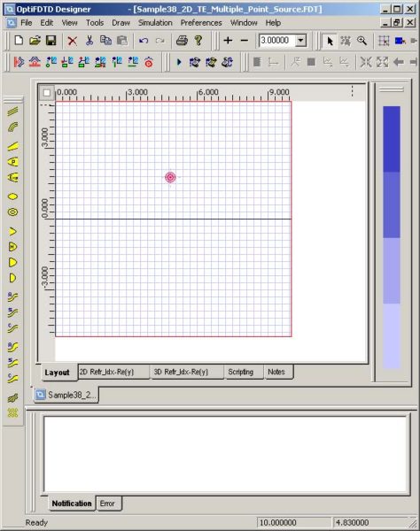
| 2 | Place the Input Plane in the layout at the desired position. A red circle indicates the location of the point source (see Figure 83). |
Figure 83: Point Source in Input Plane layout
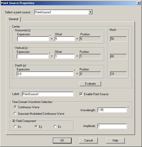
| 3 | To set up the input wave properties, double-click the Point Source in the layout.
The Point Source Properties dialog box appears. |
Figure 84: Point Source Properties dialog box
| 4 | In the Point Source Properties dialog box, set up the position information:
Note:
|
| 5 | Specify the Time Domain Waveform and enter a value in Wavelength.
Note: If you want to use Gaussian Modulated Continuous Wave, select Gaussian Modulated Continuous Wave in the Time Domain Waveform Selection dialog box. |
| 6 | Enter the Amplitude value in the Amplitude box (bottom right). |
| 7 | In the 3D Field Component area, select an electrical component to hold the point source.
Note: For 2D TE simulation, the point source is functional to major component Ey. For 2D TM simulation, point source is functional to major component Hy. Note: You can edit any point source using the Point Source Properties dialog box by making a selection from the drop-down list accessible with Select a point source. Also, multiple point sources can be placed in the same position. |


