OptiFDTD has options to use simplified Periodic Boundary Condition (PBC). It can work with other boundary conditions such as Anisotropic PML, PMC, and PEC. With PBC, you can simulate a simple plane wave simulation, or a periodic layout simulation.
For more information regarding PBC, see the Technical Background.
The following procedure is based on . You can also open the project file Sample09_2D_TE_PBG_Domain_Reduced_Square_Lattice.FDT that can be found in the Sample file folder.
Setting the 2D TE FDTD simulation parameters
| Step | Action |
| 1 | From the Simulation menu, select 2D Simulation Parameters.
The Simulation Parameters dialog box appears. |
| 2 | Type/select the following information:
Polarization: TE Mesh Delta X [μm]: 0.05 Mesh Delta Y [μm]: 0.05 |
| 3 | Click Advanced….
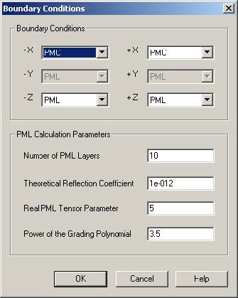
The Boundary Conditions dialog box appears. |
| 4 | Type/select the following information (see Figure 107):
-X: PMC +X: PMC -Z: Anisotropic PML +Z: Anisotropic PML Anisotropic PML Calculation Parameters Number of Anisotropic PML Layers: 10 Theoretical Reflection Coefficient: 1.0e-12 Real Anisotropic PML Tensor Parameters: 5.0 Power of Grading Polynomial: 3.5 |
Figure 107: 2D simulation parameters
| Note: The rectangular beam with PMC boundaries on the edge realizes the TE plane wave simulation for the periodic structure. | |
| 5 | In Time Parameters, click Calculate.
The default time step size is calculated. |
| 6 | Select Run for 12000 Time Steps (Results Finalized). |
| 7 | Select Key Input Information: Input Plane1 and wavelength:1.9.
Note: The input plane’s center wavelength is used for DFT calculations. |
| 8 | Click OK to close the Simulation Parameters dialog box without running the simulation, or click Run to start the OptiFDTD Simulator.
Note: Before running the simulation, save the project to a file. |
| 9 | Perform the simulation and Post-processing analysis as shown in. You will get the same result as shown in Figure 104. |


