In the previous examples we intentionally selected propagation direction (k-vector) normal to the multilayer structures. Changing the polarization from TE to TM we are getting the same results, which confirm that the TE/TM modes are degenerate. In case of an off-axis propagation the k-vector has a component parallel to the Bragg layers, and the degeneracy of TM/TE modes is lifted. The band solver allows you to investigate cases of off-axis incidence. This can be achieved by an appropriate k-path definition. We will be considering propagation along G2 reciprocal lattice vector, i.e. k=(0, k2, 0). As the ordering of the lattice vectors in the band solver is (c, a, b) due to the layout designer G2 vector in this sample will correspond to x-direction (see 2D FDTD Band Solver).
First save the current k-path in a file so that you can easily reload the path again later on. Click on ‘Save File’ and in the ‘SaveAs’ dialog box input the name, e.g. BraggZ. Next redefine the k-path by adding one more major k-point and editing the k-path in the following manner:
– k1=( 0.0, 0.0,-0.5), div=1
– k2=( 0.0, 0.0, 0.0), div=5
– k3=( 0.0, 1.5, 0.0), div=15
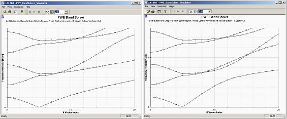
Thus the first part of the k-path from k1 to k2 will be the same as in the previous simulations but path from k2 to k3 will refer to propagation in y-direction (direction of the G2 reciprocal vector), parallel to the dielectric layers. The results of the simulations run for TE and TM polarizations are shown below.
Figure 7: Band structure of the Bragg grating for TE (left) and TM (right) polarizations. The first part of each diagram (indices 0-5) depicts on-axez propagation, where the TE and TM modes are degenerate (the same diagram) and band gaps are present. The right part of the diagrams (k-vector indices 5-20) shows lift od degeneracy and splitting of the TE/TM bands.
TE/TM solutions can also be described in the fashion of reference [1] as solutions
with electric field vector in x-direction in case of TE and electric in yz plane in case of
TM.


