| Step | Action |
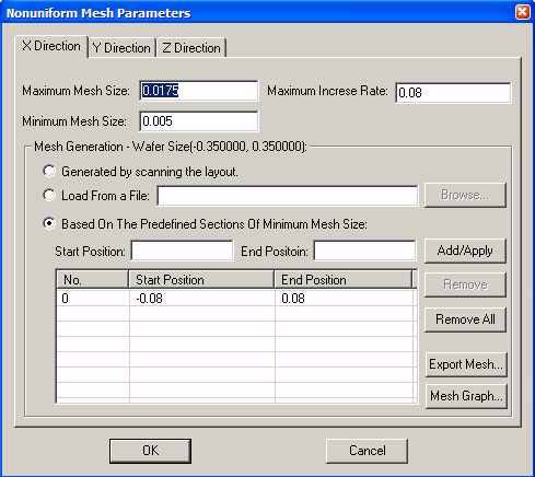
| 1 | Click Parameters in the Nonuniform Mesh Parameters region of the 3D Simulation Parameters dialog box. Nonuniform Mesh Parameters dialog box appears. (refer to Figure 1) |
Figure 1: Nonuniform Mesh Parameters
Maximum Mesh Size: The maximum mesh size value (unit in ?m) for low refractive index region.
Minimum Mesh Size: The minimum mesh size value (unit in ?m) for high refractive index region.
Maximum Increase Rate: The mesh increase rate η between two neighbor mesh Δi ± 1 = ( 1 + η) ⋅ Δi ;η is suggested between 0.01 to 0.5.
A larger mesh increase rate will make the mesh discontinuity too big, which will results in larger simulation errors.
Generated by scanning the layout: When this default mesh generation method is selected, the software will automatically scan the refractive index distribution in one direction. The Minimum Mesh Size value will be set to the highest refractive index region, while Minimum Mesh Size will be set to the lower index region.
Maximum Increase Rate will be used to smooth the mesh between the maximum and minimum mesh.
Load From a File: OptiFDTD allows the user to generate the mesh. The user can define the mesh grid coordinator value in a text file then load it into OptiFDTD to do the discretization.
Based On the Predefined Sections of Minimum Mesh Size: This discretization method allows the user to define the minimum mesh size region by inputting Start Position, End Position, then click Add/Apply button to make it function in the software. The Remove and Remove All buttons can remove selected defined regions.
Export Mesh: The mesh grid coordinator can be exported to a text file.
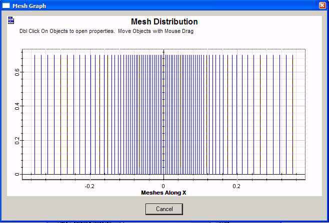
Mesh Graph: Mesh in one direction can be observed in a 2D graph.
| 2 | Click X-Direction tab to set the x-direction mesh, set the following parameters:
• Maximum Mesh Size: 0.0175 μm • Minimum Mesh Size: 0.005 μm • Maximum Increase Rate: 0.08 • Select Based On the Predefined Sections of minimum mesh size, Start position: -0.08 μm , End Position: 0.08 μm . Click Add/Apply button. This makes the silver particle in x-direction region use the minimum mesh • Click Export Mesh button to export the mesh grid coordinator into a file. Use any text editor to open the file and check the mesh grid coordinator values. • Click Mesh Graph button to observe the x-direction mesh. (Refer to Figure 2). Click Cancel button in mesh graph to return the mesh setting page.
|
Figure 2: x-direction mesh graph
| 3 | Click Y-Direction tab to set the y-direction mesh.
• Maximum Mesh Size: 0.0175 μm • Minimum Mesh Size: 0.005 μm • Maximum Increase Rate: 0.08 • Select Based On the Predefined Sections of minimum mesh size, Start position: 0.27 μm , End Position: 0.43 μm . Click Add/Apply button. This makes the silver particle in y-direction region use the minimum mesh. |
| 4 | Click Z-Direction tab to set the Z-direction mesh.
• Maximum Mesh Size: 0.0175 μm • Minimum Mesh Size: 0.005 μm • Maximum Increase Rate: 0.08 • Select Based On the Predefined Sections of minimum mesh size, Start position: 0.325 μm , End Position: 0.475 μm . Click Add/Apply button. This makes the silver particle in z-direction region use the minimum mesh. |
| 5 | Click OK in Nonuniform Mesh Parameters dialog box to accept all the settings. |
| 6 | Click advanced button in the 3D Simulation Parameters dialog box, Boundary Condition dialog box appear.
• X and Y direction boundary set as PBC • Z direction boundary set as AMPL • Number of PML Layer: 16 • Theoretical Reflection Coefficient: 1.0e-12 • Power of Grading Polynomial: 3.5 • Real AMPL Tensor Parameters: 10 Note: The above mesh setting makes the mesh close to the boundary is 0.0175 μm . So the APML tensor value can be around 5-10, in case of very small mesh around 0.005 μm , the AMPL tensor value should be around 60-90. |
| 7 | Save the new layout setting by clicking save in the file menu. |


