This part shows how to extract the diffraction angle and diffraction efficiency based the FDTD near field simulation and far-field transform. The simulation concept is to use the FDTD method to get the near field pattern and near field transmission and reflection. The diffraction angle and power ratio for different diffraction beam can be evaluated from the far-field pattern. Then the power ratio for each diffraction beam multiplies the near field transmission (or reflection) will be the grating efficiency.
The sample used in this part is a 2D periodic grating with both substrate and grooves are made of SiO2 (n=1.5). Normal incident plane waves come from the air then pass through the grooves and goes to the substrate. For such a periodic layout with normal incident plane wave, we can still pick up one unit cell to perform the simulation with transverse boundary condition set as PBC. In case of tilting angle input, more periodic cells should be used for the simulation and transverse boundary should be AMPL.
The sample file can be found in the Sample file folder, the file is named as:
“X64_sample56_2D_Caululate_Grating_Efficiency.fdt”. Please open this layout with OptiFDTD layout designer. Double clicking on each object in the layout to check the settings:
• The periodic length is 1.0 μm , the groove length is 0.5 μm , and depth is 0.15 μm . Substrate layer connects to the z-direction end, which is supposed the transmitted waves are all goes out.
• Time domain input waves is continued, wavelength is 0.63 μm , for this single wavelength simulation. We can set the input plane wave power as 1.0, then where the power in the observation line is put in the transmission region will be the transmission value.
• X-direction boundary is set as PBC
• An observation line is put after the grating, it detects the near field transmission and the field pattern
Please perform the 2D 64bit simulation for this sample layout (32bit simulation is also acceptable, but will be slower). After the simulation, open the results file to check the near field properties.
| Step | Action |
| 1 | Under tools menu, select Observation Area Analysis. |
| 2 | Select Observation Line in Observation Area Analysis dialog box. Select “Observationline1” in the observation line check list |
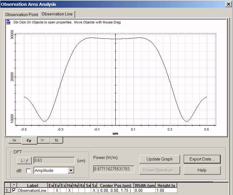
| 3 | Click Update Graph button, near field pattern along the observation line and the power value 0.9771162755 appears (refer to Figure 10). The power value shown here is the power transmission, because the input power is set as 1.0 |
Figure 10: Field pattern in Observation line
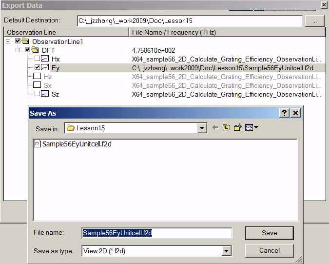
| 4 | Click Export Data button to export the field pattern alone the line. The export data dialog box appears. (Refer to Figure 11). Select the Ey components, and then right lick this Ey component to change the file folder and name. Name the exported data file as “Sample56EyUnitcell.f2d” |
Figure 11: Export near field pattern
| 5 | The exported data file is for one periodic cell. Now extend this data for 40 periodic cells so that far field transform will be more accurate. Open the exported field file by using the Notepad or other text editor.
• The first line in the data file is the version number. • The second line is data point number which is 101. • The thirds line is the observation line dimension start value and end value. • The remaining lines are complex field data. To extend the field data as for 40 periods, please do the following. a Copy the data from fifth line to the end, totaling 100 lines. b In the end of data file, paste the copied data 39 times. c Change the second line data point number as 4001. d Change the third line as -20.0 20.0. e Save the new data file as “Sample56Ey40cells.f2d” |
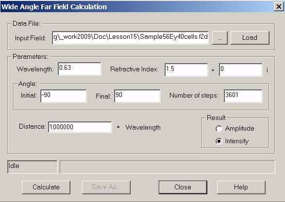
| 6 | From the OptiFDTD program start menu, select tools box and select the far field button, then select the “Wide angle far field 2D”, Wide Angle Far Field Calculation dialog box appears (refer to Figure 12) |
Figure 12: Wide angle far field calculation
| 7 | In the ”, Wide Angle Far Field Calculation dialog box,
• Click “…”, button to locate the near field file “Sample56Ey40cells.f2d” • Click Load button to load the data into the calculation • Set wavelength as 0.63 μm • Set refractive index as 1.5 • Initial angle: -90degree, final angle: 90Degree, Number of steps: 3601 • Set results as Intensity • Click Calculate button and save the results as “sample56FFP40Cells.ffp” |
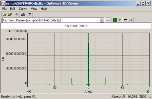
| 8 | From the OptiFDTD program start menu, select the “Opti 2D viewer”, then use it to open the far field file “sample56FFP40Cells.ffp” (refer to figure 12) |
Figure 13: Far field pattern
| 9 | In the Far field pattern, right click the graph and select the zoom in tools to zoom in each peak value, or open the data file by any text editor to read each diffraction angle and peak value. |
| Diffraction order | Angle(Degree) | Peak value |
| 0 | 0 | 3.562191e+012 |
| ±1 | ±24.82 | 4.780688e+011 |
| ±2 | ±57.14 | 3.998404e+010 |
• The diffraction angle matched the diffraction equation
• 0th-order power ratio (to the total power) can be evaluated form the peak intensity ratio. i.e.

• oth-order diffraction efficiency is power ratio multiply the near field transmission
0.7746∗0.9771 = 0.75686166


