
OptiFDTD now has options to use Perfect Electrical Conductor (PEC) and Perfect
Magnetic Conductor (PMC) boundary conditions. You can choose which boundaries
use the new conditions, and Anisotropic PML can be used for the remaining
boundaries. With this PEC/PMC/Anisotropic PML combination, the following
simulations may be obtained:
- Plane wave simulation
- Domain reduced simulation for symmetric, periodic, or photonic band gap structures
Image value of PEC/ PMC
The following graphs show the field set up in the PEC/PMC wall (zero thickness) and
its image value
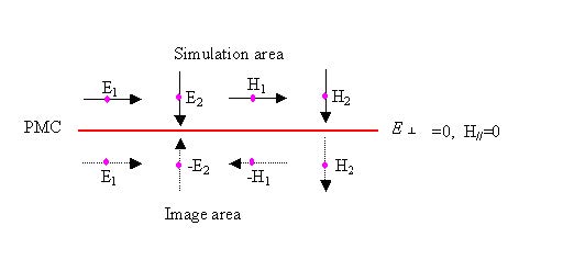
Figure 8: Field in PMC and image area
(E┴ is the vertical electric component in the PMC wall, and HII is the parallel
magnetic component in the PMC wall.)
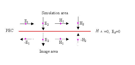
Figure 9: Field in PEC and image area
As we can see from Figure 8, PMC is a symmetric wall for the symmetric structure
with symmetric wave propagation. The following two cases details the results when
PMC occurs.
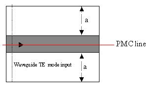
Figure 10: PMC wall in a symmetric waveguide—excited by symmetric TE waveguide mode
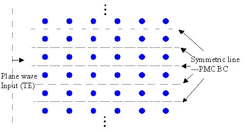
Figure 11: PMC wall in a periodic structure for TE plane wave propagation
PMC can be seen as the special case for Bloch’s boundary condition (periodic
boundary condition) where the k-vector is set to zero in the corresponding direction.
PEC line is the complement of PMC, so in Figure 10, and Figure 11, the PMC line will
become the PEC line if the wave polarization is changed to TM.
Plane wave realized in symmetric/periodic structure
Figure 12 shows how the plane wave simulation can be realized for a symmetric
structure. For a 2D TE simulation, the edge of transverse plane should be set to the
PMC boundary condition to realize the plane wave.
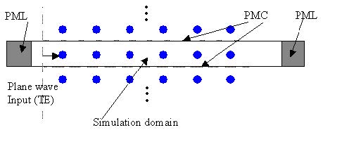
Figure 12: Plane wave in TE simulation
For a 2D TM simulation, the edge of transverse plane should set to the PEC boundary
condition to realize the plane wave.
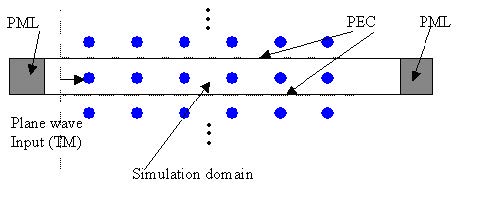
Figure 13: Plane wave in TM simulation
For a 3D simulation, the plane wave realization depends on the wave polarization and
the boundary condition setup at different edges of the transverse plane. If the wave
goes in z-direction, and the input wave is in y-direction polarization, then the y plane
(x-z) edge should be set to the PEC and x-plane (y-z plane) edge set to the PMC
boundary.
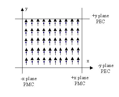
Figure 14: Y-polarization plane wave (z-direction propagation) with boundary conditions
For 3D simulation, if the wave goes in z-direction, and the input wave is in x-direction
polarization, then the y plane (x-z) edge should be set to the PMC and x-plane
(y-z plane) edge set to the PEC boundary.
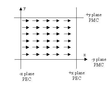
Figure 15: X-polarization plane wave (z-direction propagation) with boundary conditions
The plane wave shape can be set by setting the rectangular wave parameters in the
Input Wave Properties dialog box. Currently, plane wave does not support the tilting
angle. Currently, the plane wave simulation is only effective for symmetrical
structures.