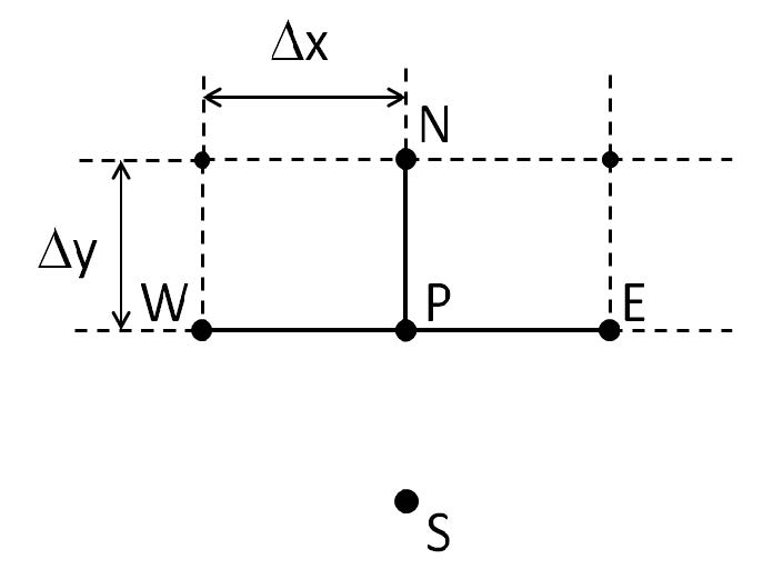
The equation (10) applies to nodes inside the mesh. Nodes on the boundaries need a different formula because at least one of the N, S, E, or W nodes will be outside of the mesh and therefore not included in the calculation. The situation for a node on the South boundary is illustrated in Fig. 3.
Figure 3: South boundary. The S node is outside the mesh, and not part of the simulation.
One kind of boundary condition is to just take the value at S to be zero. This is the Dirichlet boundary condition, where all field components are taken to be zero at (or one mesh point beyond) the simulation window boundary. This boundary will be used if the Use TBC checkbox is not selected in the Solver Parameters dialog box (Fig. 2).
If the Use TBC checkbox in the Solver Parameters dialog box is selected, the value of the magnetic field at S will be estimated. When the mode solving starts, S will be taken as 0 for the initial iterations of IRAM. After Skip Value steps (and after each multiple of Skip Value iterations) the mode solver calculates and displays the Ritz pair ( x, θ ) , which is an approximation to the mode indicated in the Preview Mode field of the Solver Parameters dialog box (Fig. 2). The x contains the values of the magnetic field at the nodes of the mesh, and the ![]() is an approximation to the propagation constant β as found in equation (8) or (9). The region outside the calculation window boundary (south of P), is without feature, of constant permittivity, and so the magnetic field (either x component or y) will approximately follow
is an approximation to the propagation constant β as found in equation (8) or (9). The region outside the calculation window boundary (south of P), is without feature, of constant permittivity, and so the magnetic field (either x component or y) will approximately follow

the approximation being due to the ![]() being only an approximation to the propagation constant. The value will approach the actual propagation constant as the number of iterations of IRAM increase.
being only an approximation to the propagation constant. The value will approach the actual propagation constant as the number of iterations of IRAM increase.
The solution of the magnetic field of a single mode in a region of constant permittivity can be represented as a plane wave
![]()
Here the origin of the coordinate system ( x, y ) is at the point P. As such, the desired value of the magnetic field at S is
![]()
and this value can be used for the node outside the calculation window when applying
finite difference equations like (10).
To calculate the appropriate value for the wavenumber, b . Put (33) in (32)
![]()
The Ritz pair estimate provides an estimate of the magnetic field at the nodes of the mesh, and these values can be used to estimate the value of ∂2 h ⁄ ∂x2 (and therefore a ) at P along the South boundary. With the a estimated this way, the b could be calculated as
![]()
where the branch cut of the square root is selected so as to have a positive real part, so that the magnitude of hS is something smaller than hP .
It remains to estimate a . This can be done by finite differences of the three nodes W, P, and E, but the values of the field at the window boundaries can be quite small, with lots of error, and the results of second differences can be erratic. In this release we chose a Fourier Series method to estimate ∂2 h ⁄ ∂x2 , and the entire South boundary is used. Let
f( x ) represent the magnetic field on the South boundary x ∈ [ 0, L ] , and let fn(x ) be a Fourier Series based approximation of f(x )

where

The fact that all of the points on the boundary are used to calculate the fn(x ) helps to stabilize it from numerical errors. The second derivative is calculated by changing the series in the appropriate way

and from the definition (33)

When using TBC, the Fourier Series estimate of a is limited to 2n + 1 terms by the parameter n . This parameter is set by the user from the Fourier Limit field of the Solver Parameters dialog box (Fig. 2).
In view (34) and (36), it is necessary to have an estimate of the eigenvalue θ to estimate hS . Because of this, OptiMode does not apply TBC in the early stages of the IRAM process. Instead, OptiMode always starts with the Dirichlet form of the problem. While the IRAM iterations progress, the Ritz Pairs ( x, θ ) are calculated and displayed. At each iteration, the progression of the eigenvalue θ is noted. Once the problem begins to show sufficient convergence on θ , the TBC is turned on. This strategy helps the IRAM from getting lost in spurious solutions early in the iterations. The point at which the boundary condition is switched from Dirichlet to TBC is user controlled. In the Change Limit field of the FD tab of the Solver Parameters dialog box, the user enters a number (see Fig. 2). The TBC will be switched on when the relative change in θ becomes less than Change Limit. Note that this θ is an estimate of the modal index of the mode displayed by OptiMode simulator during IRAM iterations. Which mode to display is selected by the user from the Preview Mode field. This selection means that the TBC will be better adapted to the mode selected in Preview Mode. Therefore we recommend setting the Preview Mode to the mode of interest. It permits viewing of that particular mode during the IRAM process, and the TBC will be a better match at the calculation window boundaries.


