A simple algorithm can be employed to simulate certain types of nonlinearities. This algorithm is currently implemented for 2D BPM and for scalar and semi vectorial isotropic 3D BPM simulations.
In non-linear simulations, the refractive index distribution is affected by the presence of an optical field. The influence of the field on the refractive index is defined by some function of the optical field. For example, in the case of the Kerr effect, the changes in the refractive index are proportional to the optical field intensity, and the refractive index distribution ![]() can be written as:
can be written as:
![]()
Here, ![]() is the position vector, n0 is the constant part of the refractive index, nKe rr is non-linear coefficient and E is the electric field intensity. Without an optical field, the refractive index is equal to n0 . Once the optical wave propagates within the material, the refractive index is affected and the change of refractive index in turn influences the optical wave. The non-linear algorithm attempts to solve the field propagation in non-linear materials using linear BPM engine by looping the propagation within a single propagation step into an iteration process.
is the position vector, n0 is the constant part of the refractive index, nKe rr is non-linear coefficient and E is the electric field intensity. Without an optical field, the refractive index is equal to n0 . Once the optical wave propagates within the material, the refractive index is affected and the change of refractive index in turn influences the optical wave. The non-linear algorithm attempts to solve the field propagation in non-linear materials using linear BPM engine by looping the propagation within a single propagation step into an iteration process.
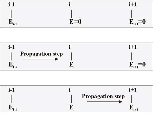
A typical BPM simulation process is shown in Figure 25. The simulation engine is called in every propagation step to propagate the optical field one step forward, i.e. from slice i to slice i + 1 .
Figure 25: Standard BPM propagation (no iteration). The shaded boxes schematically show optical field E being propagated through three consecutive slices – (i-1, i, i+1). The top box shows initial optical field in slice i-1 and undefined field values in slices i and i+1(field assigned to zero). With each propagation step, the field propagates to another slice.
If a non-linear iteration process is used, the propagation engine advances the same initial optical field several times within one propagation step, depending on specified number of iterations, before the algorithm proceeds further. During this iteration process, the refractive index is updated through the function ![]() , using the latest iteration result.
, using the latest iteration result.
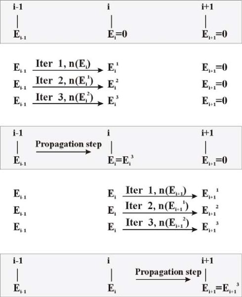
The algorithm is symbolically depicted in Figure 26. First, the initial optical field is propagated one step. Then the resulting optical field is used to calculate the new refractive index distribution within the slice. Next, the original optical field is used again as the starting field, and is propagated one step with the corrected refractive index. The iteration process is repeated the required number of times, each time using the latest iteration result to refine the refractive index value for the slice.
Figure 26: Nonlinear BPM propagation (number of iterations = 3). Before definitely advancing by one propagation step to the next slice (shaded boxes), the engine performs required number of iterations (denoted by upper index). In each of these iterations, the refractive index is corrected according to a user-specified function n(E). The index corrections are done using the previous iteration output. Notice that the initial field in the iteration steps does not change.
When using the non-linear BPM feature the non-linear waveguides must use either a User Function Profile or a User Dll Profile. Four system variables, which represent the optical field, are available to define the non-linear refractive index function; field amplitude (_Emod), field square (_EE), real and imaginary parts of the field variable (_Ere, _Eim).
The non-linear algorithm does not guarantee convergence. You must experiment with both the propagation steps and number of iterations to ensure results are converging.
Note: This feature has not yet been implemented for 3D isotropic full vector BPM and 3D anisotropic BPM engine.


